-
Less jewellery, more gold into electrotech industry! Half of the computer problems is caused by bad contacts
Exclusive caps, meters and more!Hardware Insights - power supply reviews and more! -
Re: Cheap PSU: Piece of junk or semi-decent?
Yeah, that too Less jewellery, more gold into electrotech industry! Half of the computer problems is caused by bad contacts
Exclusive caps, meters and more!Hardware Insights - power supply reviews and more!Comment
-
Re: Cheap PSU: Piece of junk or semi-decent?
Ok this is very confusing, I did my best.

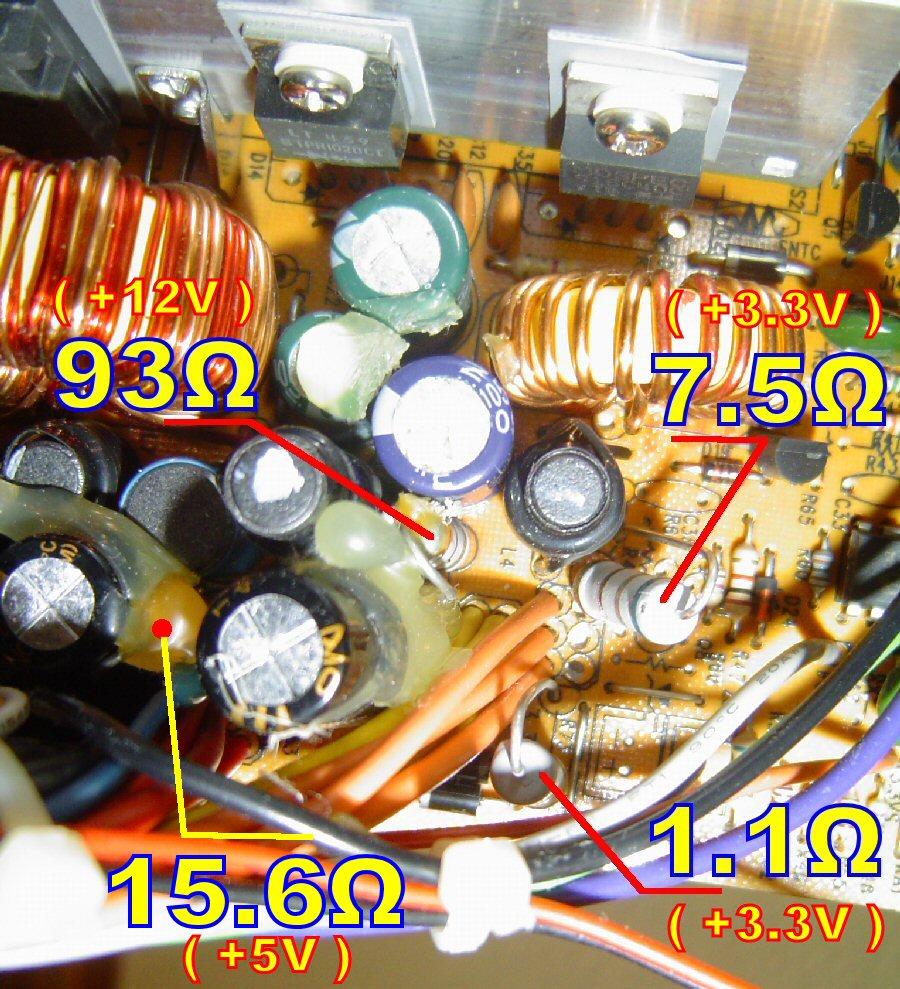
7.5Ω:
· Both resistor legs beep between them.
· Both resistor legs beep to black cable in molex.
· Leg 'A' of resistor beeps to center leg of +3.3V rectifier.
· Leg 'B' of resistor beeps to center leg of +3.3V rectifier AND to center leg of +5V rectifier.
1.1Ω:
· Both resistor legs beep between them.
· Both resistor legs beep to black cable in molex.
· Leg 'A' of resistor beeps to center leg of +3.3V rectifier.
· Leg 'B' of resistor beeps to center leg of +3.3V rectifier.
93Ω:
· Resistor legs do NOT beep between them.
· Leg 'A' of resistor does NOT beep to black cable in molex.
· Leg 'A' of resistor beeps to center leg of +12V rectifier.
· Leg 'B' of resistor beeps to black cable in molex.
· Leg 'B' of resistor beeps to center leg of +3.3V rectifier AND to center leg of +5V rectifier.Comment
-
Re: Cheap PSU: Piece of junk or semi-decent?
Well under 10 ohms it usually beeps. In these low values, go not only for sound, but also for value on DMMs display. There should be 0.0 for it to be direct joint;-) Mine DMM also shows 0 if it is under 1,5 ohm - than check that with resistance meter.
Judging from their position, 93 is on +12 V, the other two on +3,3 V.Less jewellery, more gold into electrotech industry! Half of the computer problems is caused by bad contacts
Exclusive caps, meters and more!Hardware Insights - power supply reviews and more!Comment
-
Re: Cheap PSU: Piece of junk or semi-decent?
Thanks Behemot, that cleared my rookie brainstorm .
.
7.5Ω (+3.3V rail)
· Leg 'A' of resistor beeps to center leg of +3.3V rectifier (.000)
· Leg 'B' of resistor beeps to center leg of +3.3V rectifier AND to center leg of +5V rectifier (.015)
1.1Ω (+3.3V rail)
· Leg 'A' of resistor beeps to center leg of +3.3V rectifier (.001)
· Leg 'B' of resistor beeps to center leg of +3.3V rectifier (.000)
93Ω (+12V rail)
· Leg 'A' of resistor beeps to center leg of +12V rectifier (.000)
· Leg 'B' of resistor beeps to center leg of +3.3V rectifier (.007) AND to center leg of +5V rectifier (.015).
Are the multimeter resistance readings valid while the resistors are soldered in the PCB?
BTW always in the pursuit of improving my execrable english, I've discovered that I'm incorrectly titling myself a 'noob'. What I am (or would like to be ) is a 'newbie':
'Contrary to the belief of many, a noob/n00b and a newbie/newb are not the same thing. Newbs are those who are new to some task and are very beginner at it, possibly a little overconfident about it, but they are willing to learn and fix their errors to move out of that stage.
Noobs, on the other hand, know little and have no will to learn any more. They expect people to do the work for them and then expect to get praised about it, and make up a unique species of their own.'
Urban Dictionary - NoobLast edited by TELVM; 11-10-2012, 07:42 AM.Comment
-
Re: Cheap PSU: Piece of junk or semi-decent?
That will work as well if you don't have any suitable replacement resistors. Personally, I don't like "flying" components, though, because if they are not secured well, they can short out on something. And in my experience, the short circuit protection in these Deer/Allied/L&C isn't very sensitive (actually, not at all).
It is a nice 3.3V/5V load though. I have several Radeon 9700 video cards and they pull similar power from the 3.3V/5V rails. They make the PSU rails very balanced if used in a 12V-based PC.Originally posted by TELVM
For the most part, YES. They may be off by a few Ohms, but that's okay. I usually go by the printed color code on them. And to see which rail they are on, I just remove the PSU board from its case and trace where they go to.Originally posted by TELVM
For these older Deer/Allied/L&C PSUs, I can tell you for sure that the "93" Ohm resistor is actually a 100 Ohm resistor (color code Brown, Black, Brown, Gold - just Google resistor color codes) and it's for the 12V rail. The "7.5" Ohm is likely for the 3.3V rail. The first band on its color code is blue, though, so it's actually 6.x Ohm resistor. Perhaps 6.8 Ohms? (Blue, Gray, Gold, Gold).
As for the "1.1" Ohm resistor, I'm not sure what that is on. It has too low of a resistance to be on any of the rails. If it was to be on the 3.3V rail, then it would dissipate (3.3 V ^2) / 1.1 Ohms = 9.9 Watts - and that can't be the case because judging by the resistor size, that resistor is probably only a 2 or 3 Watt rated resistor. At 9.9 Watts, it wouldn't last more than a few moments without burning. And if it was on the 5V or 12V rail, forget it - the thing would burn as soon as the power is turned on - so it can't be on those rails either.
So, for the "1.1" Ohm resistor, you would have to remove the PSU PCB from the case and follow the traces. It may be that the "7.5" Ohm resistor is connected in series with the "1.1" Ohm resistor.
If you don't want to do any PCB tracing, another way to measure the resistance of the resistors on those Deer/Allied/L&C PSUs is to connect one of your multimeter probes to a ground on the PSU (a black wire on a drive connector is perfect), and then with the other probe measure the resistance for the 12V rail (yellow wire), 5V rail (red), and 3.3V rail (orange).
Report what resistance measurements you get this way.Last edited by momaka; 11-10-2012, 10:36 AM.Comment
-
Re: Cheap PSU: Piece of junk or semi-decent?
I'm not yet familiar with resistor color codes, but I'll try:
· 93Ω: Dark brown / very dark brown or black / dark brown or dark red / gold
· 7.5Ω: Very dark blue or faded black / light brown or yellowish green / dark brown or dark red / gold
· 1.1Ω: Light red or orange / white / silver / gold
Errr not sure now what you mean by tracing. I looked for full continuity (beep + .000 in display) between the three resistors and the three rectifiers, and posted the results above.
Perhaps you mean visual tracing?:


Aye aye, here we go:... another way to measure the resistance of the resistors on those Deer/Allied/L&C PSUs is to connect one of your multimeter probes to a ground on the PSU (a black wire on a drive connector is perfect), and then with the other probe measure the resistance for the 12V rail (yellow wire), 5V rail (red), and 3.3V rail (orange).
Report what resistance measurements you get this way.
· Black molex ground to yellow molex +12V: 93Ω
· Black molex ground to red molex +5V: 15.6Ω
· Black molex ground to orange mobo connector +3.3V: 7.5ΩComment
-
Less jewellery, more gold into electrotech industry! Half of the computer problems is caused by bad contacts
Exclusive caps, meters and more!Hardware Insights - power supply reviews and more!Comment
-
Re: Cheap PSU: Piece of junk or semi-decent?
Ha, spotted a hidden resistor lurking between the output wires. And guess what, resistance between its legs reads 15.6Ω. And guess what, it zero-beeps to the center leg of the +5V rectifier:

I've perpetrated a couple guetto-mods. A header for the PSU cooling fan:


And a header for the main wires:


Now removing the PCB for fiddling is plug&play, much easier.Comment
-
Re: Cheap PSU: Piece of junk or semi-decent?
You got a hawk's eye Momaka. Found this picture of an Allied PSU from forumer Pentium4:

And mine is almost identical:

Also here is a video of a guy recapping his Allied 350W, again pretty similar to mine.Last edited by TELVM; 11-11-2012, 06:08 AM.Comment
-
Re: Cheap PSU: Piece of junk or semi-decent?
So if I get it correctly the problem with these resistors is that they dissipate much heat, and this heat can cook close-by components like capacitors. That's why you recommend replacing them with higher Ω, and hence lower W & lower heat resistors.
But these resistors must be there for some good reason (otherwise they'd discard them to save costs). Maybe they are for better crossloading management? If so perhaps it isn't such a good idea to lower its Ω.
I can think of several ways to tame the heat problem.Comment
-
Re: Cheap PSU: Piece of junk or semi-decent?
Minimum load- doesn't it say pretty much everything? On these older topologies you had to provide minimum load on every rail for the PSU to run the rails properly. Otherwise strange things could happen (voltage fluctuations, too low/too high voltage etc.). I usually do flying mod - just add some wire and pick them up into the airflow, away from caps where they can be cooled better as well.
Less jewellery, more gold into electrotech industry! Half of the computer problems is caused by bad contacts
On these older topologies you had to provide minimum load on every rail for the PSU to run the rails properly. Otherwise strange things could happen (voltage fluctuations, too low/too high voltage etc.). I usually do flying mod - just add some wire and pick them up into the airflow, away from caps where they can be cooled better as well.
Less jewellery, more gold into electrotech industry! Half of the computer problems is caused by bad contacts
Exclusive caps, meters and more!Hardware Insights - power supply reviews and more!Comment
-
Re: Cheap PSU: Piece of junk or semi-decent?

I'm thinking on something similar but a bit more radicalI usually do flying mod - just add some wire and pick them up into the airflow, away from caps where they can be cooled better as well. . The cilindrical body of a resistor isn't conductive, is it?
Comment
-
Re: Cheap PSU: Piece of junk or semi-decent?
Like I mentioned, Google resistor color codes and you will know how to read them. It's not hard and comes in very handy when you start messing with circuits more often.

The multimeter can give confusing results sometimes, so I rather go by what I see.
Boom! perfect. You got a 100 Ohm resistor on the 12V rail, 15 Ohm on the 5V rail, and 6.8 Ohm on the 3.3V rail. Judging by your underside pictures, the "1.1" Ohm resistor along with the 2 diodes next to it appears to be in some kind of load-balancing circuit between the 3.3V rail and the 5V rail. I *think* you can leave that one alone as it probably won't cause harm since it's far away from nearby capacitors.
As for the other resistors, you can do a little swapping around...
- Remove the 100 Ohm resistor from the 12V rail and put it in place of the 15 Ohm resistor. The 15 Ohm resistor you can put in place of the 6.8 Ohm resistor or put the two in series for a total of 21.8 Ohms. The latter will dissipate less heat (good for the caps) but it may also degrade the 3.3V rail regulation slightly.
Well, in this case here, you have 3 resistors dissipating about 1.5W each. It may not seem like a lot, but for the size of those resistors it is. Moreover, that's 4.5W of power your wasting for nothing. Even worse, it's 4.5W that heats the other components inside the PSU.Originally posted by Behemot
I have the same PSU as well (the LC-B300ATX 300W one below).Originally posted by TELVM
https://www.badcaps.net/forum/showpo...&postcount=491
You may not recognize it because it has less and crappier components, but the PCB design is exactly the same.
The good thing is, this PSU has extra holes on the PCB for another 5V rectifier (in case 30A is not enough ).
If the power supply is in a computer and you are loading the "right" rail (the one that the PSU was designed to be loaded on the most - for this PSU it's the 5V rail), you can go without minimum load resistors. I have a Task PSU for example, where I changed many of the load resistors. With a heavy 12V load, the PSU whines and oscillates like crazy. With a heavy 5V load, it's quiet and stable.Originally posted by Behemot
Also, on my LC-B300ATX, with the exception of the 3.3V rail load resistor, the other load resistors had much higher resistance. IIRC 270 Ohms for the 5V rail and 470 Ohms for the 12V rail.Last edited by momaka; 11-11-2012, 02:45 PM.Comment
-
Re: Cheap PSU: Piece of junk or semi-decent?
But that's it, once you will use it on 5V based system, than twice on 12V system. I better play it safe, couple watts is not such a big deal
If you manage proper airflow for the resistors, you can disipate much more heat than what they are rated for without them burning down.
TELVM: there is usually non-conductive stuff on them (either some color or ceramic-liek thing). But if you happen to damage it, you may get conductive places on the package and that is not good. Especially the ceramic-like stuff breaks easily.Last edited by Behemot; 11-11-2012, 04:52 PM.Less jewellery, more gold into electrotech industry! Half of the computer problems is caused by bad contacts
Exclusive caps, meters and more!Hardware Insights - power supply reviews and more!Comment
-
Re: Cheap PSU: Piece of junk or semi-decent?
If it's cooking my caps, it is a big deal! The load resistors on these Deer/Allied/L&C PSUs often get hot enough to discolor the PCB over time. I rather play it "unsafe" and remove/replace the resistors than be greeted with freshly baked caps the next time I open the PSU . Most of the power supplies I did this to never complained. Only my TASK PSU oscillated when there wasn't enough of a load on the 5V rail.
True. In fact, most resistors can usually withstand 2 to 4x of what they are rated for. That said, I still don't recommend to get anywhere close to what they are rated for in order to keep their temperature down. Usually 1/2 of their rating or less is what I aim for.Last edited by momaka; 11-11-2012, 05:04 PM.Comment
-
Re: Cheap PSU: Piece of junk or semi-decent?
Man, on my PSU loader I am building ATM, I am having some 10W rated resistors with 16W planned load. They have been one third the price of 20W rated
Less jewellery, more gold into electrotech industry! Half of the computer problems is caused by bad contacts
Exclusive caps, meters and more!Hardware Insights - power supply reviews and more!Comment
-
Re: Cheap PSU: Piece of junk or semi-decent?
It is bad engineering practice to use resistors above their rated load.
It is bad engineering practice to use resistors above their rated load.
It is bad engineering practice to use resistors above their rated load.
...and don't think that stuck between those caps and inductors they are going to get any significant cooling. You are kidding yourself.Please do not PM me with questions! Questions via PM will not be answered. Post on the forums instead!
For service manual, schematic, boardview (board view), datasheet, cad - use our search.Comment
-
Re: Cheap PSU: Piece of junk or semi-decent?
Write that to LC/Deer, I know that?!
Less jewellery, more gold into electrotech industry! Half of the computer problems is caused by bad contacts
Exclusive caps, meters and more!Hardware Insights - power supply reviews and more!Comment
 On the other hand keeping even the original resistor in the airflow guarantees it will not cook itself anymore.
-
 can anyone tell whether ive knackered this from the photos. In relation to black piece of something that appears to left in component in image with 156 at the end ?...05-11-2025, 05:13 PM
 -
 daxktdmb8c0
Maybe someone has a photo of a section of the board, otherwise there are no diagrams or boardview... -
Hi Everyone,
I was hoping some kind individual could provide a copy of the bios bin file for this desktop computer. I have a CH341A eprom burner. I managed to read the file and copy it back again, however, this did not fix it. The computer powers up but won't boot so the bios update program is of no use to me.
The full details of the particular model are: Compaq Presario CQ3430AN
I am attempting to repair this piece of junk for a friend of mine.
I told my friend to NEVER buy such a piece of junk in the future. HP Compaq support is virtually... -
 I have a Vizio M43-C1 stuck in a reboot loop with no backlight.
I've tested all the voltage rails coming out of the power supply and they are "normal" for this model (PS_ON & DIM go high when turned on, BL_ON & 3D_ON are close to zero due to backlight power flowing through the mainboard, 5VSB is 5V, and 12V is 19V, which is apparently normal for this board).
Basically, I get similar results to Garry in this post: https://www.badcaps.net/forum/showthread.php?t=80346
So, I've ruled out the PSU for now.
The reboot loop... -
 So the 16v 1500uF capacitor C9B1 near the power connector on the back of a Phat started leaking. Haven't been able to find the right cap, so I replaced it with a larger 25v 2200uF capacitor a couple weeks ago and everything is working fine since then. I didn't replace the other six 16v caps, they were all good.
When putting the fan plastic cover back I remember there were maybe 2-3 mm of clearance on top of it and 1-2 mm of clearance to the side of it.
For those that don't remember what the fan cover looks like I found this picture https://cdn.quade.co/wp-content/uploads/2...
Comment