Announcement

Collapse
No announcement yet.

Vizio e470va No Picture

Collapse
X
 
  • Filter
  • Time
  • Show
Clear All
new posts

    Vizio e470va No Picture

    I have a Vizeio e470va that has backlight but no picture.

    When I turn it on, I get nothing on the screen but the bezel light “VIZIO” will light up bright for the duration of the TV being on.

    About a second after the bezel lights up, the backlight will come on for about 3 seconds. During this time, the blue LED on the inverter board will come on but then will fade out after approx. 3 seconds.

    As soon and the blue light fades out, the backlight turns off for about a half a second and then then back on.

    a. The bezel light is on the entire time
    b. The blue LED comes back on and fades out after the 3 seconds

    At this point it's done doing anything and will sit like this (Bezel light on, back light on, LED not lighted on inverter).

    I have checked the voltages on the power board and at the inverter to ensure power is flowing. All seem ok. I also checked voltages coming from the main board to the T-CON. All seem ok except I couldn't get a reading on the fuse on the T-CON (see photo)


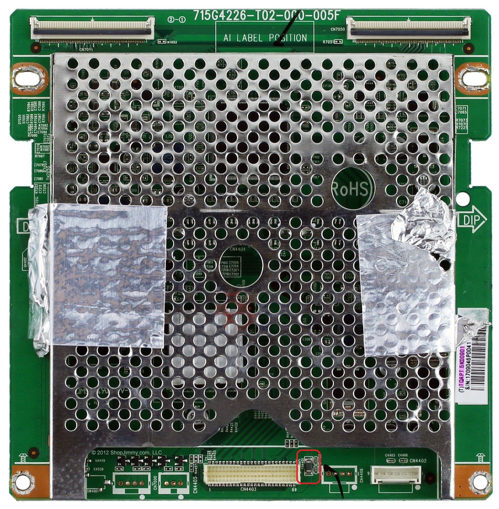
    When I check it, it reads no voltage but has continuity when powered off. I was able get a measurement on one of the small caps under the cage of the T-CON close to the fuse and it read 1.8v.

    The TV i have and the problem are identical to the one here https://www.badcaps.net/forum/showthread.php?t=38729 except he got a reading on the fuse on the T-CON and I didn't. My journey stopped there. Any ideas?

    #2
    Re: Vizio e470va No Picture

    No voltage at either side of the fuse when the set is on?

    Comment


      #3
      Re: Vizio e470va No Picture

      Can we see a pic of the back side of the TV with all boards connected?

      Comment


        #4
        Re: Vizio e470va No Picture

        you will not get any voltage to the T CON unless all systems go on the main board. Have you checked all your 3 pin LDO voltage regulators to make sure that they're all out putting a specific voltage? These are located on the mainboard
        Did I leave the soldering iron on?

        Comment


          #5
          Re: Vizio e470va No Picture

          Originally posted by newtothis View Post
          No voltage at either side of the fuse when the set is on?
          Correct. None on either side.

          Comment


            #6
            Re: Vizio e470va No Picture

            Originally posted by capleaker View Post
            can we see a pic of the back side of the tv with all boards connected?
            Attached Files

            Comment


              #7
              Re: Vizio e470va No Picture

              Originally posted by freakaftr8 View Post
              you will not get any voltage to the T CON unless all systems go on the main board. Have you checked all your 3 pin LDO voltage regulators to make sure that they're all out putting a specific voltage? These are located on the mainboard
              Checked the voltages on the 2 volt regs on the main board. both were only outputting 0.39v?

              Attached Files

              Comment


                #8
                Re: Vizio e470va No Picture

                what are the voltages on all 3 pins of both regulators?

                Comment


                  #9
                  Re: Vizio e470va No Picture

                  did you check the data sheet for those voltage regulators?, .39 seems off, maybe double check, make sure your reading them correctly.

                  Comment


                    #10
                    Re: Vizio e470va No Picture

                    yes I worked on these also before and usually what I have found is this particular board that is installed in this model and 42Inch version are known to corrupt EEPROMs
                    Did I leave the soldering iron on?

                    Comment


                      #11
                      Re: Vizio e470va No Picture

                      Originally posted by CapLeaker View Post
                      what are the voltages on all 3 pins of both regulators?
                      According to the datasheet G9084 is adjustable with voltages of 1.5V,
                      1.8V, 2.5V, 3.3V and 5.0V.

                      This is what i'm getting...

                      Pin 1 is ADJ/GND 0.00

                      Pin 2 is V out = 0.00

                      Pin 3 is V In = 0.39 v

                      Comment


                        #12
                        Re: Vizio e470va No Picture

                        Originally posted by nomoresonys View Post
                        did you check the data sheet for those voltage regulators?, .39 seems off, maybe double check, make sure your reading them correctly.
                        According to the datasheet G9084 is adjustable with voltages of 1.5V,
                        1.8V, 2.5V, 3.3V and 5.0V.

                        This is what i'm getting...

                        Pin 1 is ADJ/GND 0.00

                        Pin 2 is V out = 0.00

                        Pin 3 is V In = 0.39 v

                        Comment


                          #13
                          Re: Vizio e470va No Picture

                          Originally posted by at1105 View Post
                          According to the datasheet G9084 is adjustable with voltages of 1.5V,
                          1.8V, 2.5V, 3.3V and 5.0V.

                          This is what i'm getting...

                          Pin 1 is ADJ/GND 0.00

                          Pin 2 is V out = 0.00

                          Pin 3 is V In = 0.39 v
                          something wrong for sure, I'm having messed up readings on my samsung too, but I don't know what it means.

                          Comment


                            #14
                            Re: Vizio e470va No Picture

                            Originally posted by at1105 View Post
                            According to the datasheet G9084 is adjustable with voltages of 1.5V,
                            1.8V, 2.5V, 3.3V and 5.0V.

                            This is what i'm getting...

                            Pin 1 is ADJ/GND 0.00

                            Pin 2 is V out = 0.00

                            Pin 3 is V In = 0.39 v
                            "According to the datasheet G9084......"
                            They are not adjustable, they are fixed output, the base part number will be followed by for I.E. 18 = 1.8V fixed output. The adjustable version will not have V rating after the base P/N.
                            You are not going to get any out put when the input is only 0.39V.
                            You need to find out if the main board is sending the PSON to turn on the rest of the power supply first, if the power supplies are not turn on, then that may be the reason you are not getting the input voltage to the regulators.
                            BTW, there are more than 2 regulator ICs that I can see from the SJ pictures.
                            http://www.shopjimmy.com/catalogsear...q=Vizio+e470va
                            He also sells repair kits.
                            Last edited by budm; 02-13-2015, 03:20 PM.
                            Never stop learning
                            Basic LCD TV and Monitor troubleshooting guides.
                            http://www.badcaps.net/forum/showthr...956#post305956

                            Voltage Regulator (LDO) testing:
                            http://www.badcaps.net/forum/showthr...999#post300999

                            Inverter testing using old CFL:
                            http://www.badcaps.net/forum/showthr...er+testing+cfl

                            Tear down pictures : Hit the ">" Show Albums and stories" on the left side
                            http://s807.photobucket.com/user/budm/library/

                            TV Factory reset codes listing:
                            http://www.badcaps.net/forum/showthread.php?t=24809

                            Comment


                              #15
                              Re: Vizio e470va No Picture

                              Originally posted by budm View Post
                              "According to the datasheet G9084......"
                              They are not adjustable, they are fixed output, the base part number will be followed by for I.E. 18 = 1.8V fixed output. The adjustable version will not have V rating after the base P/N.
                              You are not going to get any out put when the input is only 0.39V.
                              You need to find out if the main board is sending the PSON to turn on the rest of the power supply first, if the power supplies are not turn on, then that may be the reason you are not getting the input voltage to the regulators.
                              BTW, there are more than 2 regulator ICs that I can see from the SJ pictures.
                              http://www.shopjimmy.com/catalogsear...q=Vizio+e470va
                              He also sells repair kits.
                              I noticed that the VIZIO logo in the front does not glow amber when plugged in. It only glows white when I push the power button on the side. I'm assuming that means that there is no standby power? Would this be an indication of no PSON signal? If not, what is the best way to test if the main board is sending the PSON signal?

                              Comment


                                #16
                                Re: Vizio e470va No Picture

                                Originally posted by at1105 View Post
                                I noticed that the VIZIO logo in the front does not glow amber when plugged in. It only glows white when I push the power button on the side. I'm assuming that means that there is no standby power? Would this be an indication of no PSON signal? If not, what is the best way to test if the main board is sending the PSON signal?
                                Some vizio TV's don't power the logo in stby or have an option to turn it off in menu.

                                It has to have Stby volts or it would not work enough to light the logo at all.

                                Best way to test ps-on is at the PSU connector labled PS-on or ON/Off. You are looking for voltage to change when power button is pressed to turn on. You will need a DMM.

                                A better pic of PSU would help.

                                Comment


                                  #17
                                  Re: Vizio e470va No Picture

                                  Originally posted by at1105 View Post
                                  Correct. None on either side.
                                  Have you try measuring the voltage on pin 49 of CN408 (T-CON CONNECTOR) on the main board with the T-CON cable disconnected?
                                  Attached Files

                                  Comment


                                    #18
                                    Re: Vizio e470va No Picture

                                    I'd be tempted to try a different mainboard, firmware may be corrupt, might be an eeprom issue, wonder if theres a mainboard repair kit for it?

                                    Comment


                                      #19
                                      Re: Vizio e470va No Picture

                                      Originally posted by MagicSmoke View Post
                                      Some vizio TV's don't power the logo in stby or have an option to turn it off in menu.

                                      It has to have Stby volts or it would not work enough to light the logo at all.

                                      Best way to test ps-on is at the PSU connector labled PS-on or ON/Off. You are looking for voltage to change when power button is pressed to turn on. You will need a DMM.

                                      A better pic of PSU would help.

                                      Before powered on, the voltage is 0v at the ON/OFF pin going to the inverter board (with the blue LED). When I power it on the voltage jumps to 5.03 and remains there. There's also a PS/On pin on the other side of the power board going out to the main board. It shows a consistent 4.78v.


                                      Attached Files

                                      Comment


                                        #20
                                        Re: Vizio e470va No Picture

                                        OK, the standby power supply is working and the main board is sending out the ps_on a and the bl-on, so now you need to check the dcV on the main filter cap's legs to see if it has >360Vdc on its two legs, you need that for the power supply to produce 12V for the main board and 24V for the inverter board.
                                        Do not touch anything with your hands or body.
                                        Never stop learning
                                        Basic LCD TV and Monitor troubleshooting guides.
                                        http://www.badcaps.net/forum/showthr...956#post305956

                                        Voltage Regulator (LDO) testing:
                                        http://www.badcaps.net/forum/showthr...999#post300999

                                        Inverter testing using old CFL:
                                        http://www.badcaps.net/forum/showthr...er+testing+cfl

                                        Tear down pictures : Hit the ">" Show Albums and stories" on the left side
                                        http://s807.photobucket.com/user/budm/library/

                                        TV Factory reset codes listing:
                                        http://www.badcaps.net/forum/showthread.php?t=24809

                                        Comment

                                        Working...