Re: Task TK-940TX-DF Blowing fuse
I'm pretty sure that i've removed all the components that i just put back on.
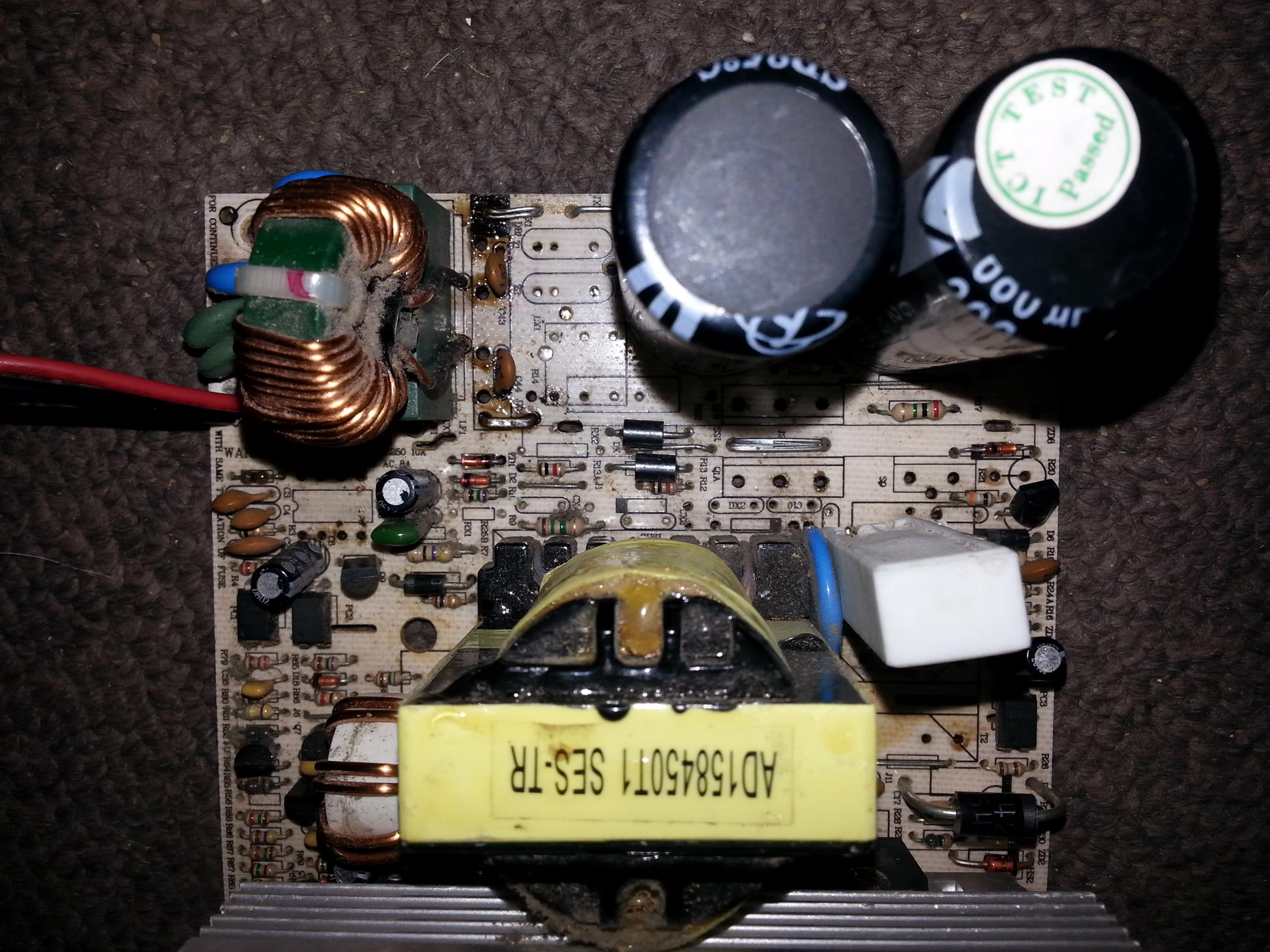
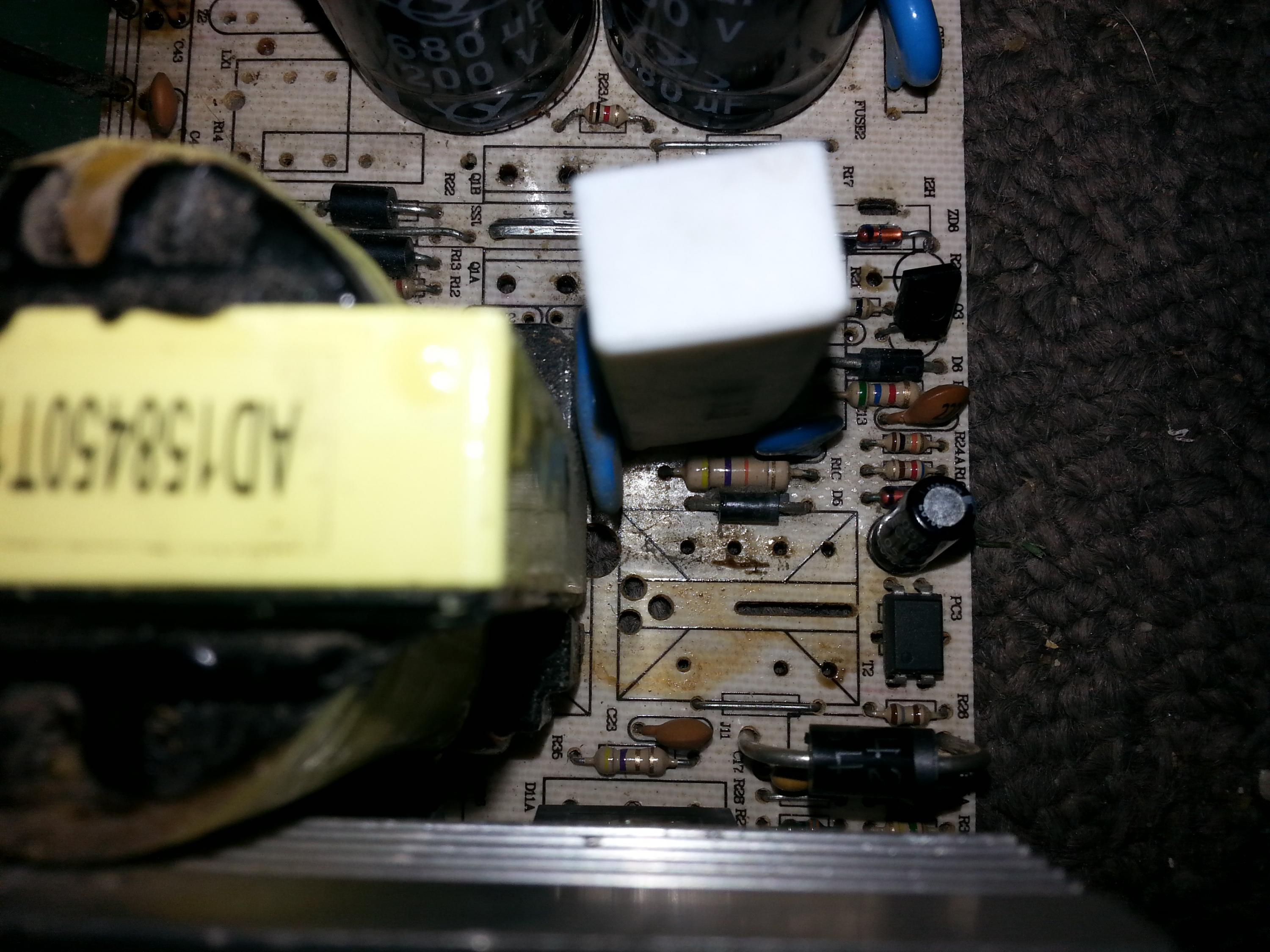
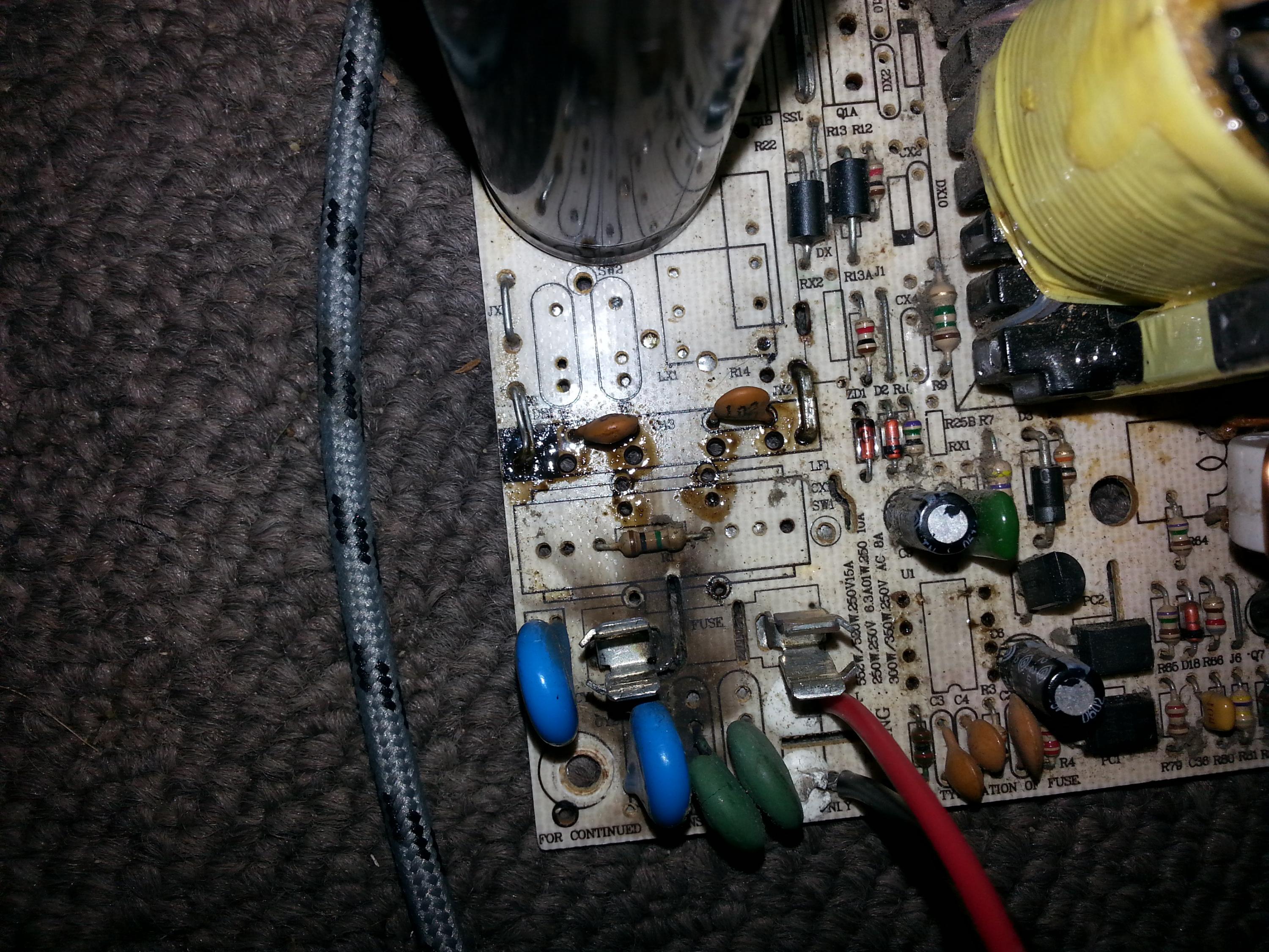
Have included a photo, just in case you can spot any that i've missed, or should have removed
But the bulb is still glowing.
So i tested the AC and CD sides separately at the rectifier circuit board holes, and noticed that 1MΩ again that i previously couldn't find (so it wasn't due to my body resistance, although coincidentally that what it roughly measured while holding onto the test leads normally) it was hidden under the X capacitor. So the AC side looks normal, and i've put the capacitor and coil back on.
And there is no short on the DC side.
I thought that the 1MΩ might not be due to a resistor, because i didn't see it on a schematic that i was looking at (attached below) - but it obviously does (and shouldn't there be one of these in the schematic?)
What's the function of that resistor, as i'm picking that it's not a discharge resistor for the primary capacitors, as it looks like R1 and R2 in the schematic would do that job.
And as any short arising (which neither of my meters is showing) across the DC side, looking at the the schematic, could something be going on with those two transistors that is causing a short when the power is switched on? (assuming that my PSU is similar enough to that - hey, it's got two BJT transistors on the primary, and has an LM339, which looks like it's for the 5VSB)
Unfortunately, no fuse in this one - thanks for the tip though.
[URL="https://www.badcaps.net/forum
I'm pretty sure that i've removed all the components that i just put back on.
Have included a photo, just in case you can spot any that i've missed, or should have removed
But the bulb is still glowing.
So i tested the AC and CD sides separately at the rectifier circuit board holes, and noticed that 1MΩ again that i previously couldn't find (so it wasn't due to my body resistance, although coincidentally that what it roughly measured while holding onto the test leads normally) it was hidden under the X capacitor. So the AC side looks normal, and i've put the capacitor and coil back on.
And there is no short on the DC side.
I thought that the 1MΩ might not be due to a resistor, because i didn't see it on a schematic that i was looking at (attached below) - but it obviously does (and shouldn't there be one of these in the schematic?)
What's the function of that resistor, as i'm picking that it's not a discharge resistor for the primary capacitors, as it looks like R1 and R2 in the schematic would do that job.
And as any short arising (which neither of my meters is showing) across the DC side, looking at the the schematic, could something be going on with those two transistors that is causing a short when the power is switched on? (assuming that my PSU is similar enough to that - hey, it's got two BJT transistors on the primary, and has an LM339, which looks like it's for the 5VSB)
Did you try removing/unwinding/cutting the the isolating tape on the transformer? A lot of traffos hide the fuse in there. Usually it's a square box fuse, kind of looking like a small X2-class safety cap.
[URL="https://www.badcaps.net/forum
Attached Files


Comment