
Hello everybody,
I have an issue on my Focal Cub 3 subwoofer unit : it stays desperately off.
The main fuse and the 2 MOSFET's are not blown.
Here is a picture of the main psu board :
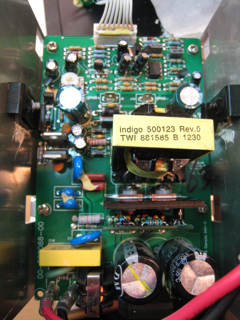
As you can see on the picture, the 2 MOSFET's are driven by a tiny pcb board vertically soldered on the main pcb board "INDIGO 660038RA".
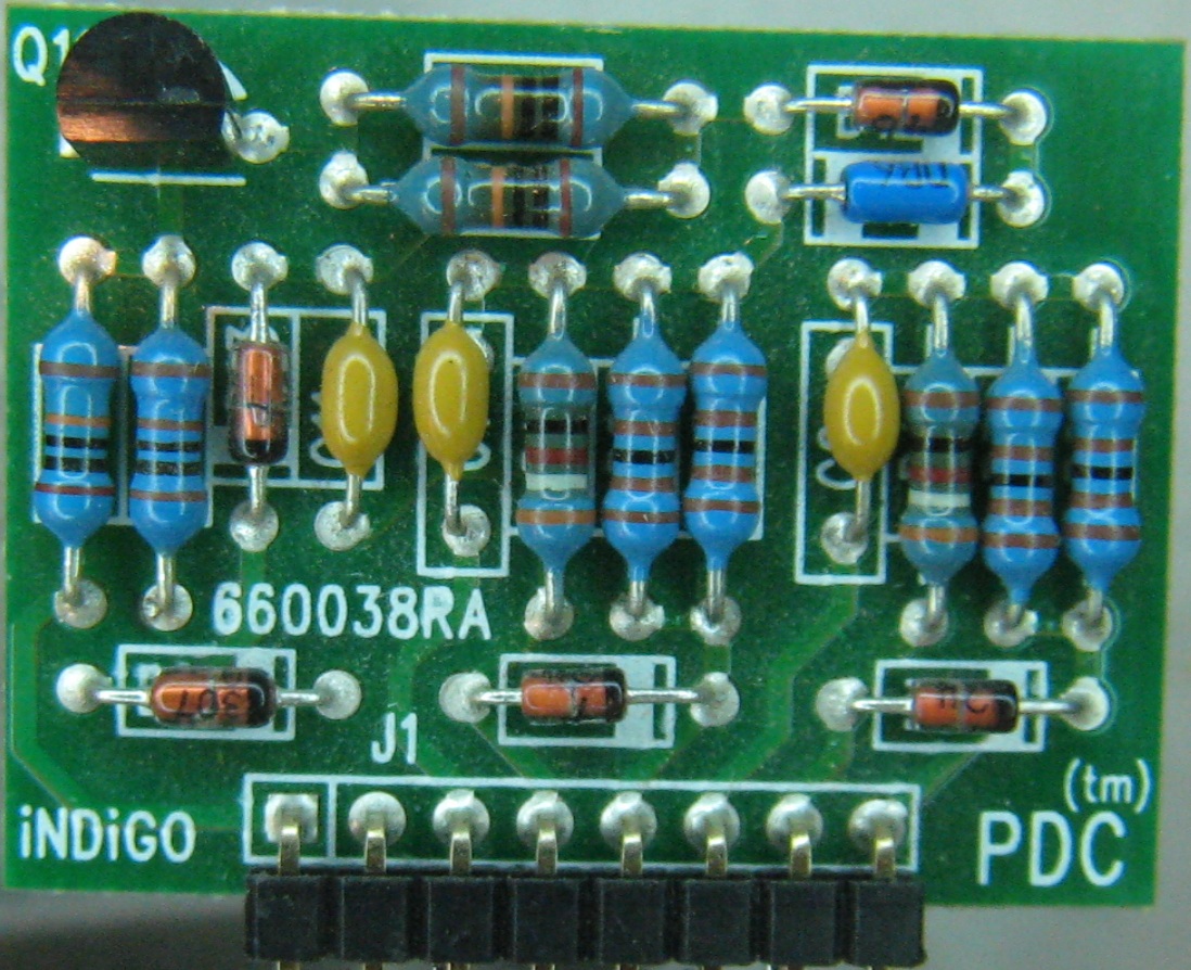
From left to right, the pin 5 and 8 are connected to the gates of the MOSFET's.
As I saw weird colors on the resistors, I changed all the resistors, all the diodes and all the capacitors on the tiny pcb board. The DB6 diac (hard to find !) and the MPSA92 transistor are the only survivors...
I even replaced the 2 MOSFET's with IRF740 (IRF730 originally)...
After replacing all that components, the voltages on the pin of the board are still the same...
From left to right :
120V
350V
119V
119V
119V (-> gate MOSFET)
0V
0V
0V (-> gate MOSFET)
It changed nothing.
One day, as I was doing some tests, I don't know what happened but the unit started...
I measured the following on the pins.
From left to right :
166V
342V
87V
150V
179V (+ square wave with the oscilloscope)
-20V
15V
+20V (+ square wave with the oscilloscope)
As I had to leave home, I turned the unit off and when I came back... nothing... and still nothing since that "holy" day...
I go on with my investigation...
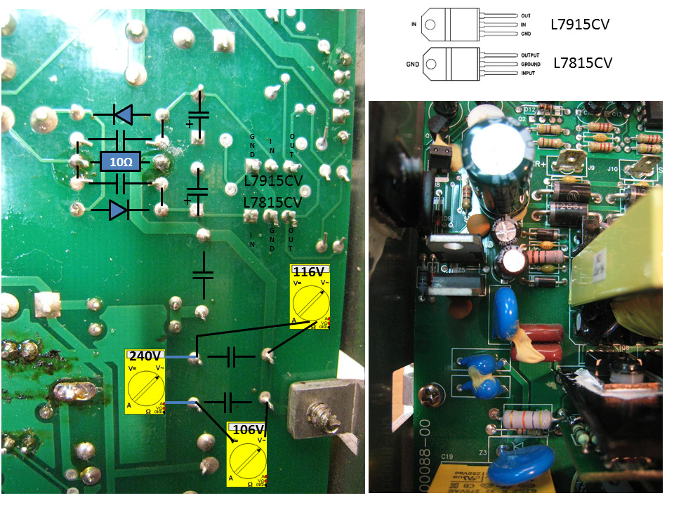
Now, I'm wondering what is the purpose of an area of the main pcb : the 240V is directly connected thru 2 (X1 Y1) capacitors to the secondary. I guess this is a "step down circuit"... The value of the 2 capacitors is 100pF. I don't know which voltage I should have after this two capacitors... and I don't know what should be my reference point for measurement. Currently I have 0V between the GND and the OUT pins of both L79(78)15CV regulators.
I regret not to have done some measurements on the regulators the only day it worked...
Here are the top view and the bottom view of this part.
According to you what should I measure in the different areas of this part ?
Would it be interesting to change the X1, Y1 capacitors ?
It is hard to me to understand the whole operation of this unit...
Any help will be appreciated.
Thanks a lot !
I have an issue on my Focal Cub 3 subwoofer unit : it stays desperately off.
The main fuse and the 2 MOSFET's are not blown.
Here is a picture of the main psu board :
As you can see on the picture, the 2 MOSFET's are driven by a tiny pcb board vertically soldered on the main pcb board "INDIGO 660038RA".
From left to right, the pin 5 and 8 are connected to the gates of the MOSFET's.
As I saw weird colors on the resistors, I changed all the resistors, all the diodes and all the capacitors on the tiny pcb board. The DB6 diac (hard to find !) and the MPSA92 transistor are the only survivors...
I even replaced the 2 MOSFET's with IRF740 (IRF730 originally)...
After replacing all that components, the voltages on the pin of the board are still the same...
From left to right :
120V
350V
119V
119V
119V (-> gate MOSFET)
0V
0V
0V (-> gate MOSFET)
It changed nothing.
One day, as I was doing some tests, I don't know what happened but the unit started...
I measured the following on the pins.
From left to right :
166V
342V
87V
150V
179V (+ square wave with the oscilloscope)
-20V
15V
+20V (+ square wave with the oscilloscope)
As I had to leave home, I turned the unit off and when I came back... nothing... and still nothing since that "holy" day...
I go on with my investigation...
Now, I'm wondering what is the purpose of an area of the main pcb : the 240V is directly connected thru 2 (X1 Y1) capacitors to the secondary. I guess this is a "step down circuit"... The value of the 2 capacitors is 100pF. I don't know which voltage I should have after this two capacitors... and I don't know what should be my reference point for measurement. Currently I have 0V between the GND and the OUT pins of both L79(78)15CV regulators.
I regret not to have done some measurements on the regulators the only day it worked...
Here are the top view and the bottom view of this part.
According to you what should I measure in the different areas of this part ?
Would it be interesting to change the X1, Y1 capacitors ?
It is hard to me to understand the whole operation of this unit...
Any help will be appreciated.
Thanks a lot !
Attached Files
if you find these attachements useful please consider making a small donation to the site


Comment