Is this bad??

Collapse
X
 
  • Time
  • Show
Clear All
new posts
  • stevo1210
    Badcaps Legend
    • Oct 2006
    • 4156
    • Australia

    #1

    Is this bad??

    Hello Everyone,

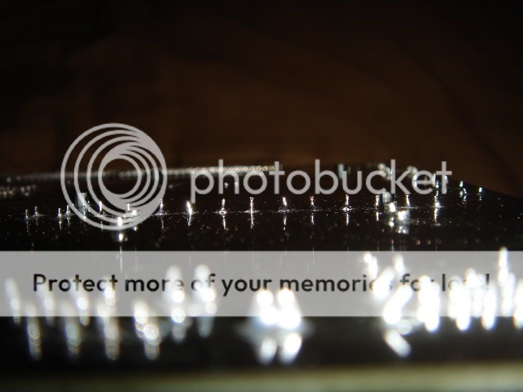
    I have a Gigabyte GA-8IG1000-G Motherboard that came out of RMA not that long ago. Before I installed it back into my PC, I could see something that looked quite bad.
    There are a bunch of traces that lead to the CPU that have some damage to them??
    The traces were originally a blue colour because my PCB is blue. Now the traces that have been scratched across have turned a whitish colour. I'm just wondering if thats the top layer of PCB colouring gone or have the traces been permanently damaged??
    The board still works well with no stability issues. In fact i'm posting on that PC now.

    I took some photos, but the flash is preventing the traces from being seen.... I don't know any way to get around this. Putting the flash off on the digital camera will cause the image to blur. I have no idea of getting around this.

    Thanks.
    Don't find love, let love find you. That's why its called falling in love, because you don't force yourself to fall, you just fall. - Anonymous
  • toastygoodness
    Badcaps Veteran
    • Jul 2005
    • 813
    • United States

    #2
    Re: Is this bad??

    maybe it's just glue?

    Comment

    • tazwegion
      Badcaps Veteran
      • Jun 2006
      • 444
      • Australia

      #3
      Re: Is this bad??

      I'm thinking it may be merely a scratched clear coating which is placed over PCB's to protect them from corrosion, that would give an opaque appearance

      BTW doesn't your digital camer have a macro setting? I use this plus the zoom feature combined with natural light for all my shots (still perfecting my technique)
      Viva LA Retro!

      Comment

      • stevo1210
        Badcaps Legend
        • Oct 2006
        • 4156
        • Australia

        #4
        Re: Is this bad??

        Originally posted by tazwegion
        I'm thinking it may be merely a scratched clear coating which is placed over PCB's to protect them from corrosion, that would give an opaque appearance
        I checked again, it definitely isnt a clear coating, it's a deep graze type of thing. I can feel it as my fingers go across it. It isn't very deep, but it's there.

        Originally posted by tazwegion
        BTW doesn't your digital camer have a macro setting? I use this plus the zoom feature combined with natural light for all my shots (still perfecting my technique)
        I use a Sony DSC-T5 digital camera.... those very small flat looking ones. I have macro on, but without flash, the whole thing blurs out.
        I don't think there is any way I can adjust this camera in any other way since it is an automatic.

        Thanks.
        Don't find love, let love find you. That's why its called falling in love, because you don't force yourself to fall, you just fall. - Anonymous

        Comment

        • Shroomie
          Badcaps Veteran
          • Apr 2006
          • 356

          #5
          Re: Is this bad??

          My digital camera's a Kodak EasyShare CX4200, low-midrange 2 megapixel from a few years ago. Doesn't even have a macro setting. If I want to get a decent picture of a PCB, I take the board in question out and stand it up out on the porch with the sunlight on it, then get the camera as close as I can and still have it be in-focus. That's the only way I've gotten a really clear picture, since I don't have any fluorescent lights (which also help this camera out) at my disposal.

          Hope this helps.
          You know there's something wrong when you open up a PSU and are glad to find Teapos.
          Why I don't buy cheap cases!

          Comment

          • stevo1210
            Badcaps Legend
            • Oct 2006
            • 4156
            • Australia

            #6
            Re: Is this bad??

            This one's a bit off topic but.... it still relates to PCB scratches and damage areas.

            I have another motherboard, a Achieva Australia V845SX motherboard (PC Partner OEM). It's a socket 478 motherboard that runs on SDRAM and uses a VIA P4X266A Chipset.
            It had bad Licon caps to start off with, then it was recapped with a bunch of Hitano 3300uf 10V, 12.5mm caps.... and the worst happened, some of the foil in the capacitor holes had come loose and fallen out, taking along with it some PCB paint. It happened when i was cleaning out the holes by stuffing a new cap in....


            The picture above shows what happened in the first round of recapping the board, but the board still worked and booted Windows. No big problems, I lived with it for over 6 months.


            Then because the caps were oversized for the 10mm spaces, and dust started to clog in the capacitor leads....they had to be removed again....
            This time, the same kept happening and I even changed my "solder cleaning" methods. I used the needle and the desoldering braid.... and I didnt heat it for over 10 seconds either....


            .... Picture above shows the foil pieces from the cap leads still came off the board.... same with the paint in those areas.
            Frustrated, I removed the CMOS battery and dipped it into water to clean the flux and loose solder pieces....Then it was stored into an empty box.

            Yesterday, after 4 months or so, I took it back out to see if anything could be done, I tried adding doler to the damaged foil areas, instead it doesn't stick to the raw PCB but instead flows into the hole where the foil is....

            Can this damage still be repaired in any way?? or am I going to have to trash this motherboard??.... It's a good board that runs on SDRAM and it did cost a lot of money back in 2002.... so I don't really want to throw it out....
            Last edited by stevo1210; 07-10-2007, 07:57 AM.
            Don't find love, let love find you. That's why its called falling in love, because you don't force yourself to fall, you just fall. - Anonymous

            Comment

            • starfury1
              Badcaps Legend
              • May 2006
              • 1256

              #7
              Re: Is this bad??

              Humm if the via's (the hole with metal) are still intact you might get away with a bit of missing top copper if it doesn't connect anyway.

              Unfortunately MB PCB are multilayer PCB's and if a via is gone then possibly its stuffed.

              I don't design MB PCB's so have no idea how they connected up the caps and how they do the ground planes (these are somewhat critical with the VRM circuit I believe) etc in the MB.

              also you have probably weaken the structure of the holes too so I guess if they are there its going to be a one shot affair drop them in and hope it works.

              If they are VRM caps you may get away with larger values in fewer spots.
              to get the total capacitance (see my gigabyte board post)
              but it really depends on whats damaged and whats not.
              What purpose the damaged one's are for.

              The short answer is bin it

              but if you are prepared to have a real close look at the via's work out what the purpose of each of the caps is you may find a work around to it.

              I suppose it really depends on how desperate you are to save this board but remember even if it does fire up there may be further issues if via's have been removed.

              There are 2 I can see, (1 in the top right and bottom right) that the via may be gone in...

              anyway its up too you

              Oh and learn the Needle trick K
              Last edited by starfury1; 07-10-2007, 08:33 AM.
              You step into the Road, and if you don't keep your feet, there is no knowing where you may be swept off to." Bilbo Baggins ...

              Comment

              • shadow
                Badcaps Veteran
                • Feb 2007
                • 732
                • Australia

                #8
                Re: Is this bad??

                As long as there is foil still inside, it can be saved. When soldering just make sure you get more solder on the inside of the hole and you should be fine. It is not exactly the best thing to have this problem, however it is not the end of the world. It is just very bad if you have no foil at all! I guess you would have to get the solder to flow through the whole hole. You may need additional flux to make this easier if at all possible. I am not sure if it is possible to save a hole if there is no foil at all.

                Comment

                • Rainbow
                  Badcaps Legend
                  • Aug 2005
                  • 1371

                  #9
                  Re: Is this bad??

                  You can always use a piece of wire. If the capacitor was connected in parallel with the one next (left) to it, just leave one leg of the new cap longer and solder it to the left. It's not going to look pretty but nobody looks on bottom of a board when installed in a case.

                  Comment

                  • stevo1210
                    Badcaps Legend
                    • Oct 2006
                    • 4156
                    • Australia

                    #10
                    Re: Is this bad??

                    Originally posted by Rainbow
                    You can always use a piece of wire. If the capacitor was connected in parallel with the one next (left) to it, just leave one leg of the new cap longer and solder it to the left. It's not going to look pretty but nobody looks on bottom of a board when installed in a case.
                    That's a good idea actually, but since there's still some foil left inside the damaged hole, will that have any impacts on the capacitance of the VRM input??

                    Currently, the board uses all 3300uf 6.3V caps for VRM input and output....
                    Don't find love, let love find you. That's why its called falling in love, because you don't force yourself to fall, you just fall. - Anonymous

                    Comment

                    • stevo1210
                      Badcaps Legend
                      • Oct 2006
                      • 4156
                      • Australia

                      #11
                      Re: Is this bad??

                      Originally posted by starfury1
                      The short answer is bin it
                      I can see that it's a lot of work so I guess I'll have to use it for spare parts (there's a bunch of MLCC's that will probably be useful)...... I'm going to find another board though.... I have so much SDRAM here.... I have to find a P4 SDRAM motherboard now.
                      eBay will probably have all the answers to an SDRAM motherboard......
                      Don't find love, let love find you. That's why its called falling in love, because you don't force yourself to fall, you just fall. - Anonymous

                      Comment

                      • Rainbow
                        Badcaps Legend
                        • Aug 2005
                        • 1371

                        #12
                        Re: Is this bad??

                        Originally posted by stevo1210
                        That's a good idea actually, but since there's still some foil left inside the damaged hole, will that have any impacts on the capacitance of the VRM input??

                        Currently, the board uses all 3300uf 6.3V caps for VRM input and output....
                        Use ohmmeter to check if the holes are connected in parallel. If they are, it's not problem, just connect the leg to the "good" hole nearby. If they are not, find a nearby point that's connected with the damaged hole and solder the leg there.

                        It's not a rocket science - if a soldering pad is damaged, you just have to find where it goes and solder the part there or use a piece of wire (if it's not close enough).

                        Comment

                        • stevo1210
                          Badcaps Legend
                          • Oct 2006
                          • 4156
                          • Australia

                          #13
                          Re: Is this bad??

                          Originally posted by Rainbow
                          Use ohmmeter to check if the holes are connected in parallel. If they are, it's not problem, just connect the leg to the "good" hole nearby.
                          I used an ohmmeter to check the continuity of the holes and they definitely are connected.
                          That means that they are connected in Parallel then, which means I can connect the leg to the nearby holes.

                          Oh, I also found the proper caps for this board too. I'll be using 3300uf 6.3V 10mm Sanyo WG series capacitors.

                          Thanks.
                          Don't find love, let love find you. That's why its called falling in love, because you don't force yourself to fall, you just fall. - Anonymous

                          Comment

                          • beauty123
                            New Member
                            • Jun 2007
                            • 2

                            #14
                            Thanks!That's Great!


                            __________
                            401(k) Plans

                            Comment

                            • stevo1210
                              Badcaps Legend
                              • Oct 2006
                              • 4156
                              • Australia

                              #15
                              Re: Is this bad??

                              Yesterday afternoon upon opening my mailbox I found a bag of Sanyo WG series caps that I purchased on eBay had been delivered.

                              So today i decided to recap this PC Partner motherboard. I tested my luck on the damaged foil holes and to my amazement, the motherboard booted powered up and POSTed too.

                              In regards to the damaged foil holes on the motherboard, As I heated the holes up and applied some solder, the solder started filling up the middle parts of the holes, so all the caps are properly in now.... since this method worked, I didn't have to connect the legs of the caps in the damaged holes to the other caps which were in the holes which were still good.

                              After finishing up, I used the Ohm meter again to see if the caps in the damaged holes were still connected to the rest in parallel, and it turns out that they still were.

                              The 3300uf 6.3V Sanyo WG caps I ordered this time look very neat and well presented compared to last time when I used 12.5mm Hitano caps....
                              Now i have a bunch of spare Hitano 3300uf 10V caps to look at.

                              Thanks.
                              Last edited by stevo1210; 07-26-2007, 03:02 AM.
                              Don't find love, let love find you. That's why its called falling in love, because you don't force yourself to fall, you just fall. - Anonymous

                              Comment

                              • shadow
                                Badcaps Veteran
                                • Feb 2007
                                • 732
                                • Australia

                                #16
                                Re: Is this bad??

                                It is always nice to hear a successful recap job.
                                Congratulations!!

                                Comment

                                • starfury1
                                  Badcaps Legend
                                  • May 2006
                                  • 1256

                                  #17
                                  Re: Is this bad??

                                  Good one Stevo1210

                                  Haven't been around so haven't had a chance to reply

                                  Nice to see you got it going and sounds as if none of the via's had been plucked out
                                  There are always possible work arounds but if possible try not to damage the PCB....
                                  (I know this is hard when you are learning though...and even sometimes it happens to those that have lots of experience)

                                  Yeah Doh should have mentioned continuity testing

                                  (rushing a bit on that reply)

                                  As to my "short answer", that was only in regard to removed via and possible damage
                                  to internal traces (and is the board worth the time and possible trouble)

                                  But like I said I don't know what they do so its hard to tell
                                  (from what I understand the pcb design is part of the VRM design as a total to its functionality)

                                  Still glad to hear its fired up and is working

                                  Cheers Mate
                                  You step into the Road, and if you don't keep your feet, there is no knowing where you may be swept off to." Bilbo Baggins ...

                                  Comment

                                  • stevo1210
                                    Badcaps Legend
                                    • Oct 2006
                                    • 4156
                                    • Australia

                                    #18
                                    Re: Is this bad??

                                    Originally posted by starfury1
                                    Nice to see you got it going and sounds as if none of the via's had been plucked out
                                    There are always possible work arounds but if possible try not to damage the PCB....
                                    (I know this is hard when you are learning though...and even sometimes it happens to those that have lots of experience)
                                    Thanks starfury and shadow for the congrutulations.
                                    In regards to PCB damage, during previous recap jobs, there were scratches all over the area around the VRM and also the damaged foil bits.... well, after all this was my first board that started recapping on about 1 year ago.

                                    But everything worked out nicely so i'm quite happy.... all I need now is a CPU and that's about it. I've got RAM and all the small bits and pieces (graphics card, case etc.....)

                                    Thank you everybody for the advice and help.
                                    Don't find love, let love find you. That's why its called falling in love, because you don't force yourself to fall, you just fall. - Anonymous

                                    Comment

                                    • stevo1210
                                      Badcaps Legend
                                      • Oct 2006
                                      • 4156
                                      • Australia

                                      #19
                                      Re: Is this bad??

                                      Here are some photos of my finished recapping job. First time I recapped a motherboard with no cold or broken solder joints.


                                      I never thought this board would ever boot up again after I damaged the foil around the caps.... that was 6 months ago and that also forced me to buy a newer Gigabyte GA-8SG800 motherboard and a new stick of DDR RAM. The Gigabyte board is very nice and very reliable with all the caps on the board being Rubycon MBZ series caps.... though it started crashing after a while from driver issues and I think also from the PSU, which I haven't checked out yet.

                                      Now I think I also need a new CPU retainer bracket.... I accidentally melted one of the mounts while recapping it.
                                      I knew I should have removed it from the board.... after i smelt burnt plastic....


                                      Thanks.
                                      Last edited by stevo1210; 07-28-2007, 08:45 AM.
                                      Don't find love, let love find you. That's why its called falling in love, because you don't force yourself to fall, you just fall. - Anonymous

                                      Comment

                                      • Harvey
                                        Badcaps Veteran
                                        • Apr 2007
                                        • 264

                                        #20
                                        Re: Is this bad??

                                        How did you manage to scratch the varnish so bad (3rd Pic)? I can't see it affecting anything though as it stands, but there's one long scratch that goes over a number of thin tracks, probably connecting to the CPU - damage one of those and you've got a tricky repair on your hands.

                                        My first thought is that your soldering iron isn't hot enough (or not clean enough) and your struggling to get the caps out?

                                        Comment

                                        Related Topics

                                        Collapse

                                        • jeremy96
                                          PS4 Power Button Traces
                                          by jeremy96
                                          Hi everyone,

                                          I recently bought a used PS4 and discovered that the power button is broken. Upon closer inspection, I found that the traces for the power button on the PCB are damaged and torn.

                                          Does anyone know where these traces lead or have any advice on how to repair them?

                                          Thanks in advance for your help!​...
                                          05-26-2024, 05:01 AM
                                        • acedogblast
                                          Guide to transplant MEC1503 EC chip and EEPROM reprogamming for T14s gen 2 and X13 gen 2
                                          by acedogblast
                                          This is a guide that I am writing for helping others to replace their MEC1503 EC chip if it breaks (or to get around an inconvenient prompt to the BIOS). This forum has been extremely helpful to me so I would like to contribute to help others. I will tell you right now that this task is very difficult to do. You MUST have experience and tools to do precision micro-soldering, BGA reballing, trace repair, and general laptop repair skills.

                                          There are some specialty tools needed to do this task. The replacement MEC1503 chips can be acquired from Aliexpress. Do not buy the bare chips as...
                                          11-02-2024, 05:13 PM
                                        • computerden
                                          PS5 EDM-020 Caps on encoder to apu traces
                                          by computerden
                                          Hey,

                                          Got a ps5 here no display, either white light or plusing blue. no display in safemode.
                                          but there are missing caps after the encoder on the traces to the apu
                                          there was one i was able to find half attatched and got it back on,

                                          what would i replace these with?
                                          is there any compatible ones i could nab off a ps4?...
                                          05-19-2023, 04:58 AM
                                        • questore
                                          GL553VW pictures need to restore traces
                                          by questore
                                          Dear All.

                                          My GL553VW motherboard shuts down durring windows boot.
                                          I have narrowed it down to an area where NDVVS_PWROK signal traces are handled barbaric way before.

                                          To restore the original pathes I need a good picture of the area to figure out where Point 3 and Point 4 are going and are they connected?
                                          Problematic area is around JP9306

                                          Made a picture where I have the problem. (sorry about the bad image quality)...
                                          11-04-2022, 08:24 AM
                                        • eccerr0r
                                          repairing traces...on a fine pitch board?
                                          by eccerr0r
                                          Well I need to repair a trace... ... on a DIMM.

                                          These tracks are tiny! What, hair line traces?

                                          Fortunately the track is fairly long, maybe 1cm, and fortunately 1mm away from the next trace. Now I need to remove the soldermask. However this trace must be thin from top to substrate as well, how could I guarantee mechanical scraping wont abrade the track? What would one use to scrape off the soldermask for these hairline traces?

                                          I guess the next thing after removing the solder mask is that the track needs to be jumpered. 30AWG Kynar wire is huge compared...
                                          04-11-2021, 11:58 PM
                                        • Loading...
                                        • No more items.
                                        Working...