
Alright, I finally busted open my Rosewill and recapped it. I took plenty of pictures, for 370. I couldn't find any markings telling who OEMd it, so hopefully he'll be able to tell.
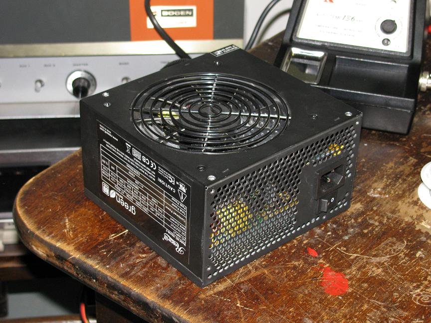
Here it is, on my work table:
Here's the label. Pretty accurate, I think. It has a big transformer, but the 33A on the 12v might be pushing things just a little....and there's something strange about the 12v, but more about that later.

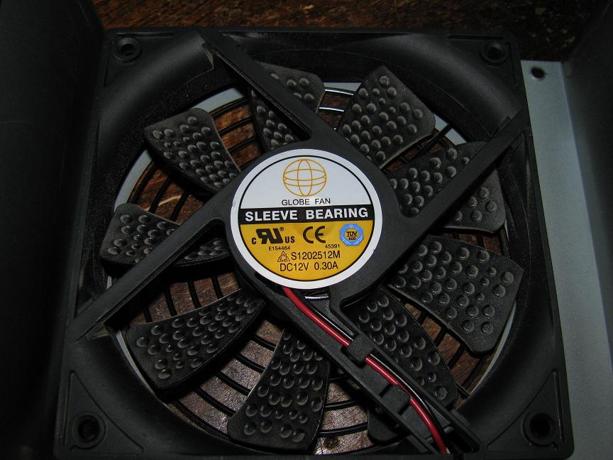
Here's the fan. Lame sleeve bearing, but the blades are dimpled so it's nearly silent, and it never runs very fast because the unit is 80+, and the case has dust filters, so I'm going to leave it for now.
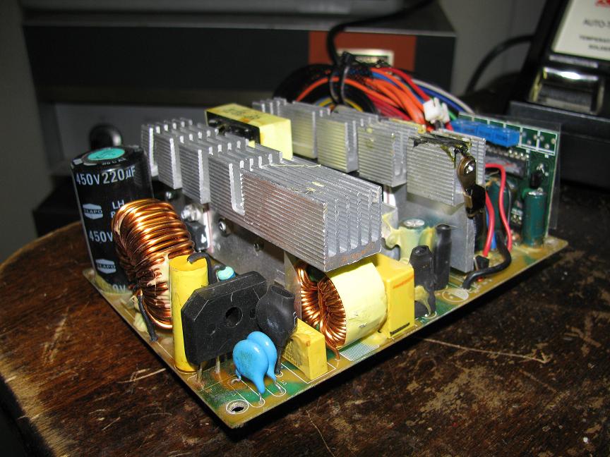
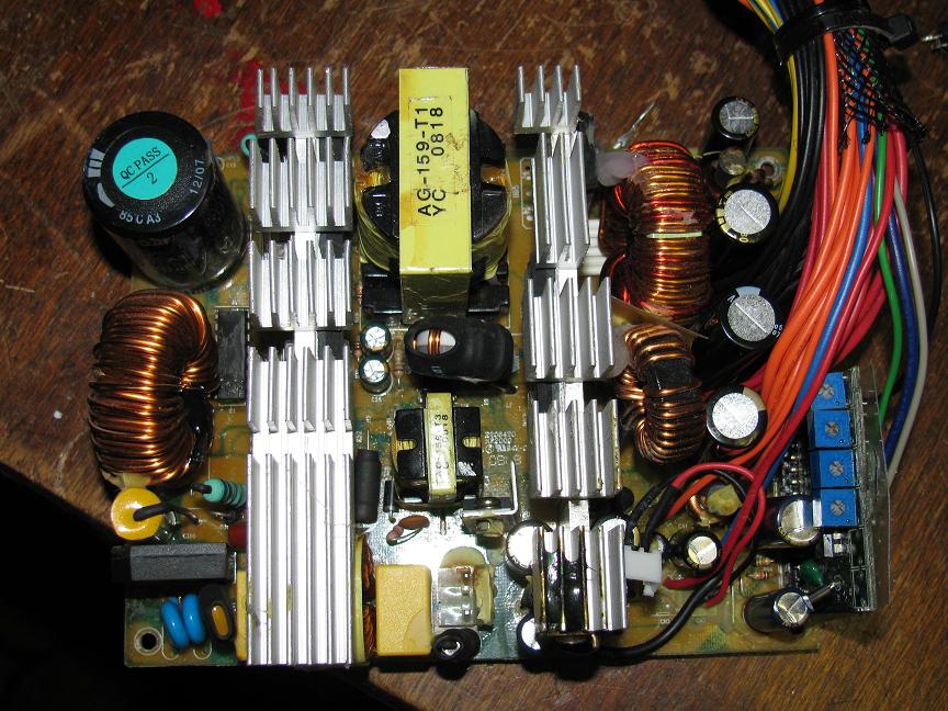
Here's an overall view - every cap is (was) a teapo. Now only the 400v one is:

Here's the input side. Impressive input filter! Total (including by the AC receptacle) there are 3 X caps, 4 Y caps, 2 coils, and an MOV. The yellow cylinder behind the bridge rectifier is 1uF cap, I don't think it's X or Y rated though. I think it's for the APFC input.
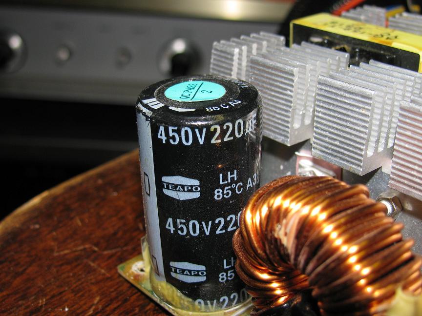
Here's the main filter cap - lame teapo 85C, but the top was flat and I didn't have anything to replace it with so I just left it. It should be fine for a while
Here's an overall shot outside of the case. I'm not sure what the pots are for. Only the ATX 24 pin connector is sleeved, but the hole in the case is grommetted so I'm not worried.
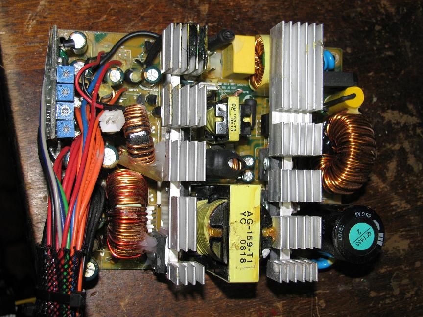
Here's the secondary side. You can't see many of the caps due to the OCP board sticking up. Also notice the lovely mess of hot glue + poorly cut plastic sheet on the back of it to keep it from shorting. There was also one of these on the solder side where all the wires come in, but I had to remove it to replace the caps.

The secondary side replacements went thusly:
+5vsb
1x 2200uF @ 10v Teapo SC and 1x 1000uF @ 10v Teapo SC -> 1x 2200uF @ 10v Rubycon MCZ and 2x (yes, two) 1200uF @ 6.3v Panny FC
-12v
2x 470uF @ 16v Teapo SC -> 1x 1200uF @ 16v Panny FM and 1x 680uF @ 16v Panny FM
+3.3v
1x 3300uF@ 10v Teapo SC and 1x 2200uF @ 10v Teapo SC -> 1x 5600uF Panny FM and 1x 2700uF Panny FC
+5v
2x 3300uF @ 10v Teapo SC -> 1x 5600uF @ 10v Nichicon HE and 1x 1500uF @ 10v Panny FM
+12v
2x 2200uF @ 16v Teapo SC -> 1x 1200uF @ 16v Panny FM and 1x 3300uF @ 16v Panny FM
all listings are in order of first cap -> PI filter coil -> second cap -> output wires. Each of the major rails got a 12.5mm cap, which I was able to jam in, and the -12v got a 10mm and an 8mm instead of 2 8mm caps.
So here's a picture after that much work:
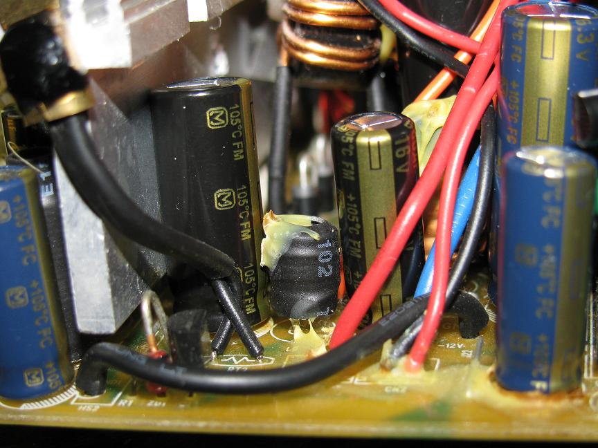
Here we have the first part of the 5vsb filter (it has 2 caps after the inductor, one isn't visible). Also, that little heatsink has the 5vsb rectifier bolted to it.

Here's the -12v PI filter. Not often do you see a full PI filter on such a useless rail! The out of focus cap way on the right is the last part of the 5vsb
And here we have another shot of the secondary side - those 12.5mm caps are huge!
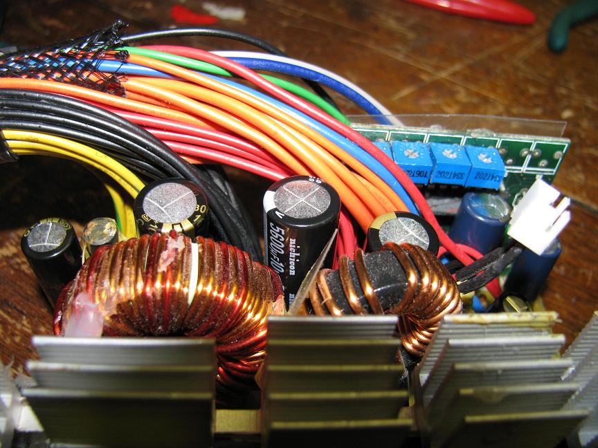
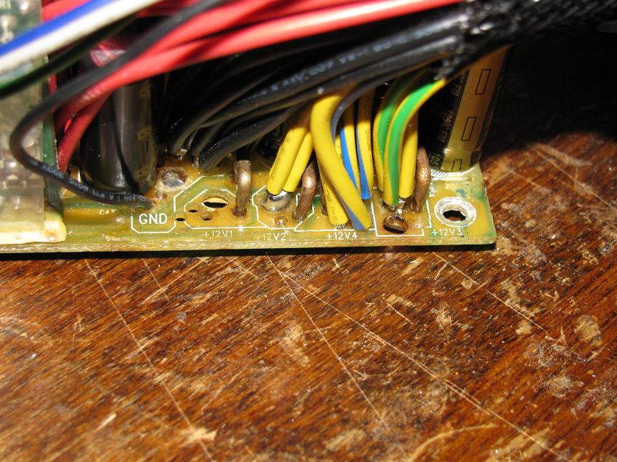
And here's a close up of the 12v wire lands. Interesting anomaly, there is nothing connected to 12v1! Other than the OCP chip, of course. 12v2 is connected to the PCIE (which I don't use), 12v3 is connected to the 4+4 pin ATX12V/EPS12V connector, and 12v4 is connected to the 24 pin ATX connector, the molex connectors and the SATA connectors.
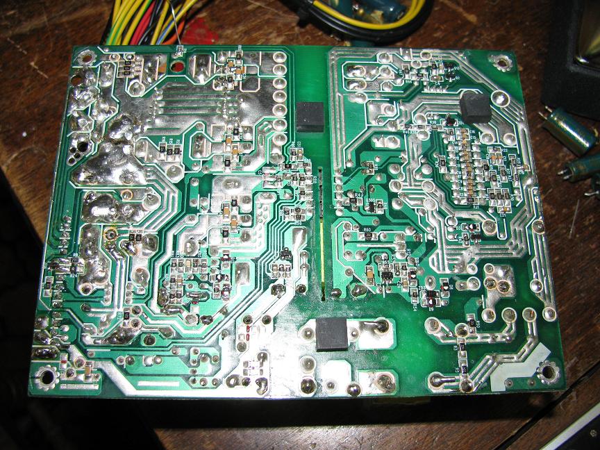
Here is the solder side of the unit. Not the best soldering I've ever seen...but not the worst! Lots of little SMD resistors and capacitors, but I didn't run into any problems with them.
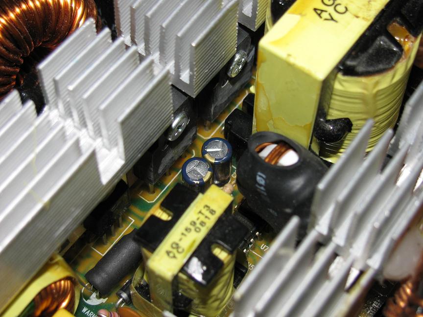
There were two little 47uF @ 50v caps on the primary side, Teapo SC of course, which I replaced with Panny FC. In the back you can see the primary switching transistors, with the part numbers scratched off. ALL the part numbers, on all the ICs and to-220 and to-247 parts were scratched off. So, I don't know exactly how much current the 12v rectifier can handle, so I don't know if the 33A rating is any good. Each major rail has a to-247 package schottky pack, so I assume they're pretty good.
And apparently there's a 15 image attachment limit, so I'll finish up in another post....
Here it is, on my work table:
Here's the label. Pretty accurate, I think. It has a big transformer, but the 33A on the 12v might be pushing things just a little....and there's something strange about the 12v, but more about that later.
Here's the fan. Lame sleeve bearing, but the blades are dimpled so it's nearly silent, and it never runs very fast because the unit is 80+, and the case has dust filters, so I'm going to leave it for now.
Here's an overall view - every cap is (was) a teapo. Now only the 400v one is:
Here's the input side. Impressive input filter! Total (including by the AC receptacle) there are 3 X caps, 4 Y caps, 2 coils, and an MOV. The yellow cylinder behind the bridge rectifier is 1uF cap, I don't think it's X or Y rated though. I think it's for the APFC input.
Here's the main filter cap - lame teapo 85C, but the top was flat and I didn't have anything to replace it with so I just left it. It should be fine for a while
Here's an overall shot outside of the case. I'm not sure what the pots are for. Only the ATX 24 pin connector is sleeved, but the hole in the case is grommetted so I'm not worried.
Here's the secondary side. You can't see many of the caps due to the OCP board sticking up. Also notice the lovely mess of hot glue + poorly cut plastic sheet on the back of it to keep it from shorting. There was also one of these on the solder side where all the wires come in, but I had to remove it to replace the caps.
The secondary side replacements went thusly:
+5vsb
1x 2200uF @ 10v Teapo SC and 1x 1000uF @ 10v Teapo SC -> 1x 2200uF @ 10v Rubycon MCZ and 2x (yes, two) 1200uF @ 6.3v Panny FC
-12v
2x 470uF @ 16v Teapo SC -> 1x 1200uF @ 16v Panny FM and 1x 680uF @ 16v Panny FM
+3.3v
1x 3300uF@ 10v Teapo SC and 1x 2200uF @ 10v Teapo SC -> 1x 5600uF Panny FM and 1x 2700uF Panny FC
+5v
2x 3300uF @ 10v Teapo SC -> 1x 5600uF @ 10v Nichicon HE and 1x 1500uF @ 10v Panny FM
+12v
2x 2200uF @ 16v Teapo SC -> 1x 1200uF @ 16v Panny FM and 1x 3300uF @ 16v Panny FM
all listings are in order of first cap -> PI filter coil -> second cap -> output wires. Each of the major rails got a 12.5mm cap, which I was able to jam in, and the -12v got a 10mm and an 8mm instead of 2 8mm caps.
So here's a picture after that much work:
Here we have the first part of the 5vsb filter (it has 2 caps after the inductor, one isn't visible). Also, that little heatsink has the 5vsb rectifier bolted to it.
Here's the -12v PI filter. Not often do you see a full PI filter on such a useless rail! The out of focus cap way on the right is the last part of the 5vsb
And here we have another shot of the secondary side - those 12.5mm caps are huge!
And here's a close up of the 12v wire lands. Interesting anomaly, there is nothing connected to 12v1! Other than the OCP chip, of course. 12v2 is connected to the PCIE (which I don't use), 12v3 is connected to the 4+4 pin ATX12V/EPS12V connector, and 12v4 is connected to the 24 pin ATX connector, the molex connectors and the SATA connectors.
Here is the solder side of the unit. Not the best soldering I've ever seen...but not the worst! Lots of little SMD resistors and capacitors, but I didn't run into any problems with them.
There were two little 47uF @ 50v caps on the primary side, Teapo SC of course, which I replaced with Panny FC. In the back you can see the primary switching transistors, with the part numbers scratched off. ALL the part numbers, on all the ICs and to-220 and to-247 parts were scratched off. So, I don't know exactly how much current the 12v rectifier can handle, so I don't know if the 33A rating is any good. Each major rail has a to-247 package schottky pack, so I assume they're pretty good.
And apparently there's a 15 image attachment limit, so I'll finish up in another post....
Attached Files
if you find these attachements useful please consider making a small donation to the site


Comment