Here’s one I’ve had for a while that I haven’t posted: a CyberLink CWT-320ATX, rev C. As the model number suggests, it’s a Channel Well unit (or CWT for short), even though the UL number points to “REAL POWER ENTERPRISE CO LTD” (actually, the last time I checked, which was over a year ago, I think that UL number might have been leading to some other name… but regardless, it’s a CWT unit).
Let’s start with a case picture:
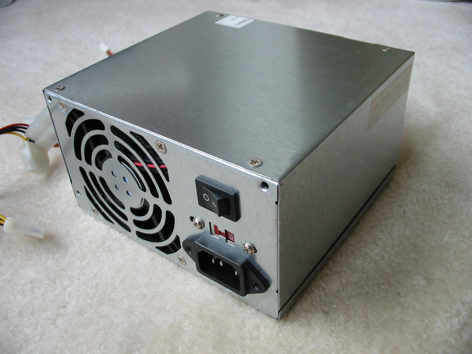
Perhaps familiar? It’s a power supply that often comes bundled with many cheap cases (though not necessarily under the name of CyberLink). This gem came with a computer I found next to a dumpster. I have another PSU very much like this – a TurboLink (that I haven’t posted pictures of yet). Same case, same QC sticker on the side with all of its various stamps, and of course, similar lack of weight and cables.
Label on the CyberLink:
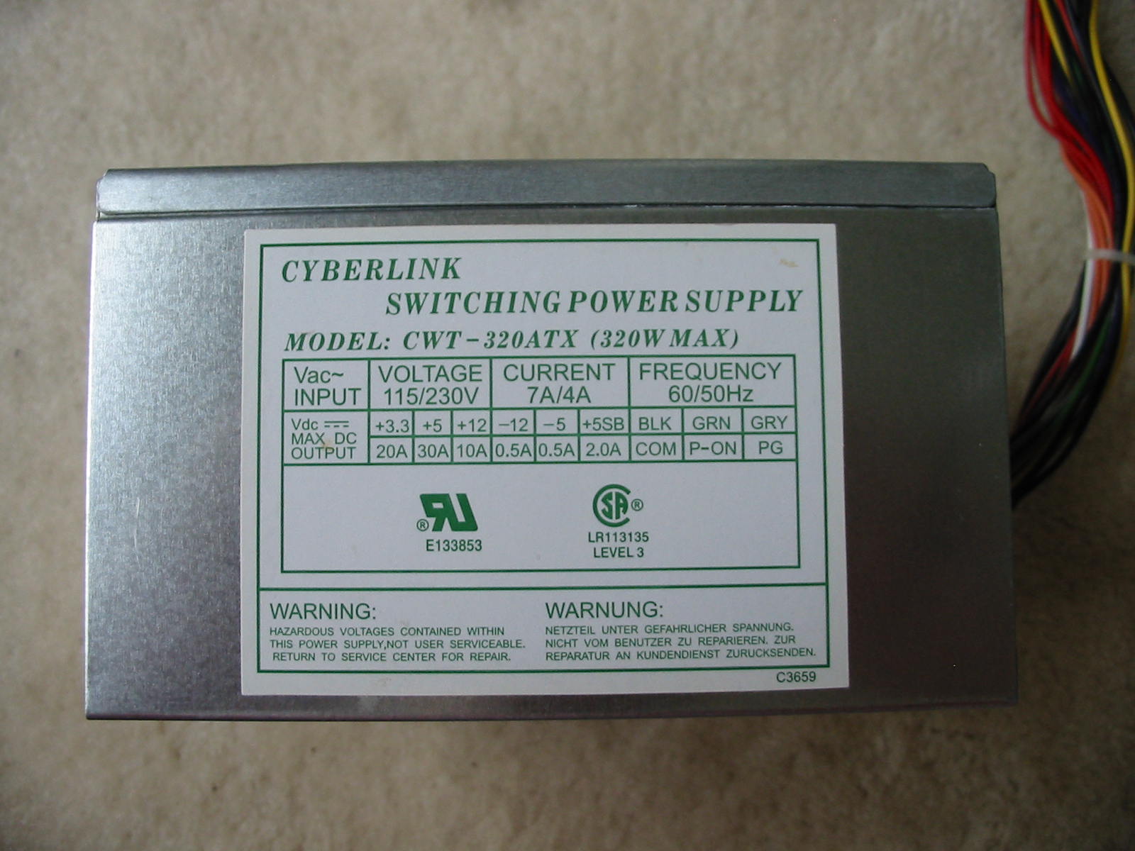
320W max? Okay, not too overrated, it seems. Let’s see some internal shorts already. The underside of the PCB…
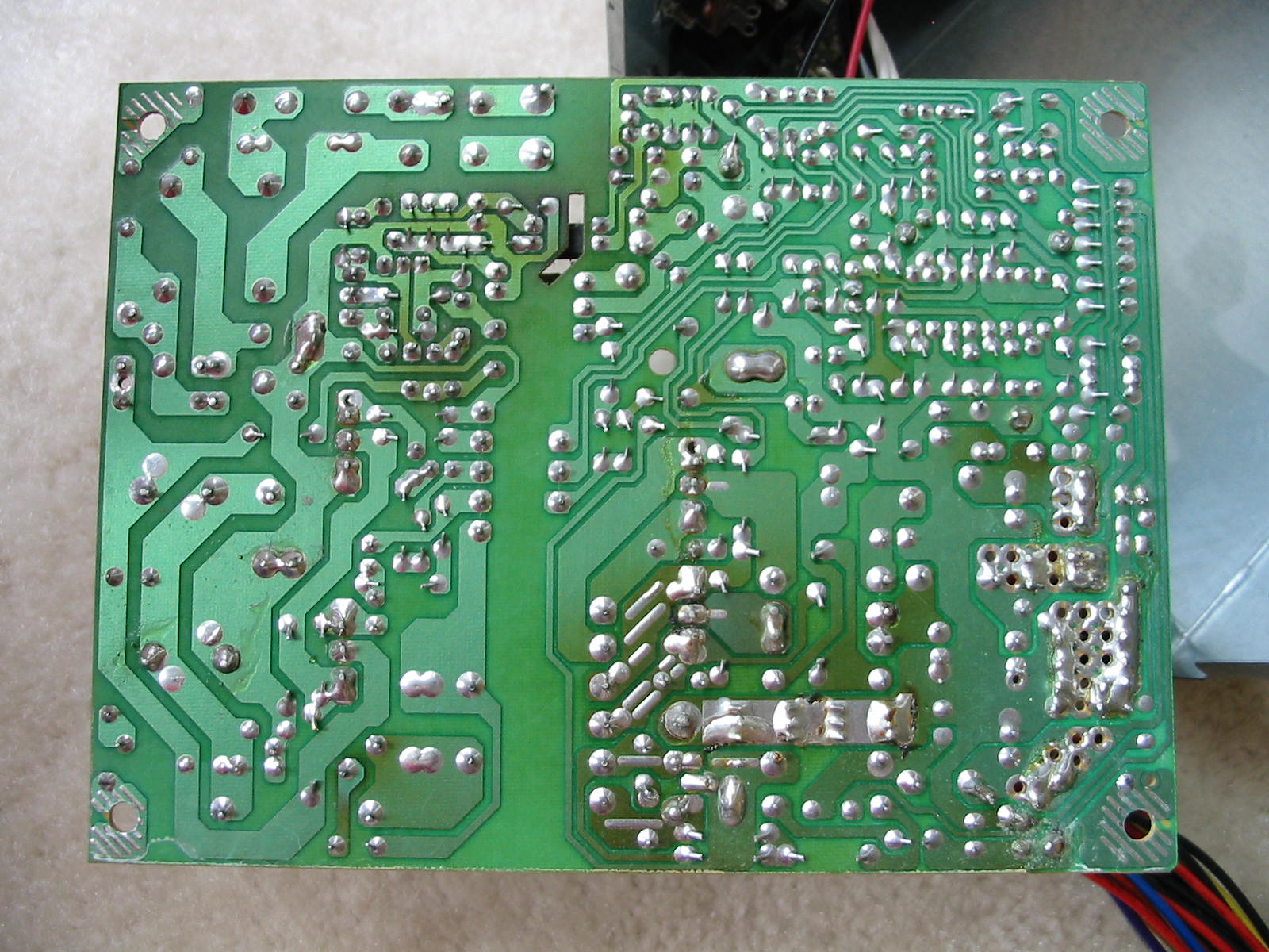
… and we already see some heat marks. Not a good start, I suppose. Soldering is not all too bad, though – certainly better than cheap Sun Pro PSUs and probably many others. Spacing between traces on the primary side is decent.
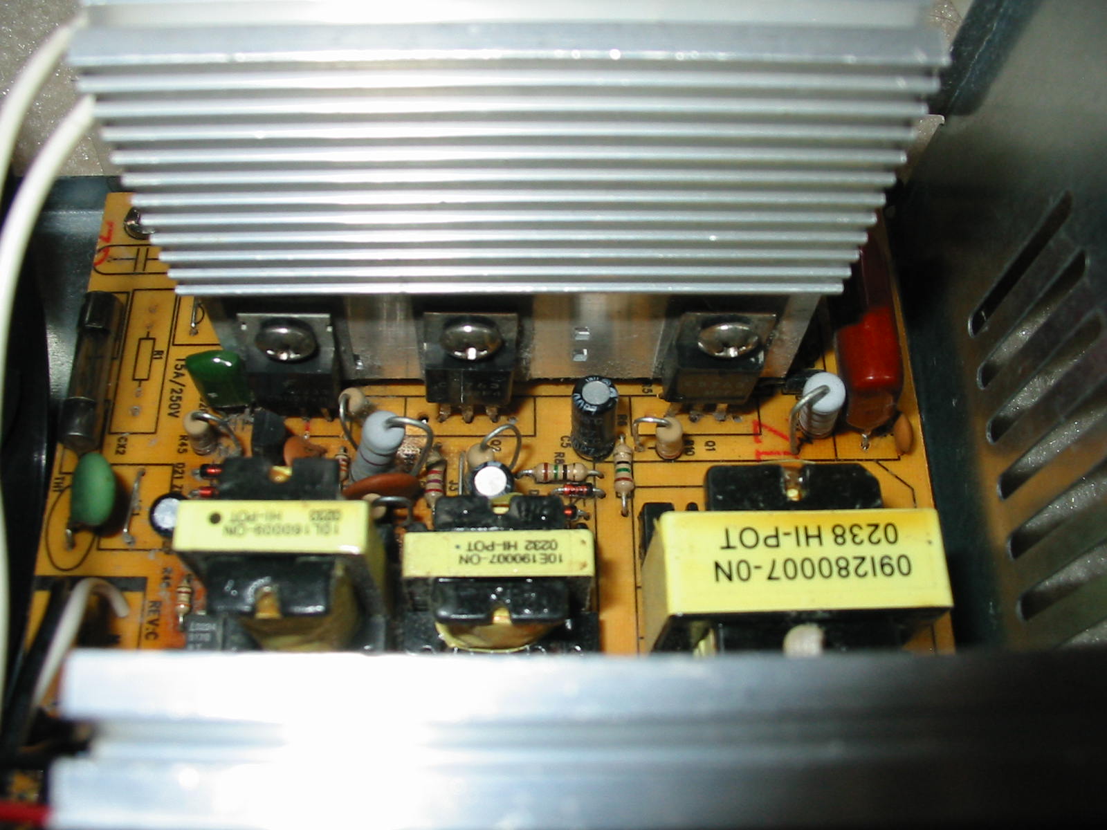
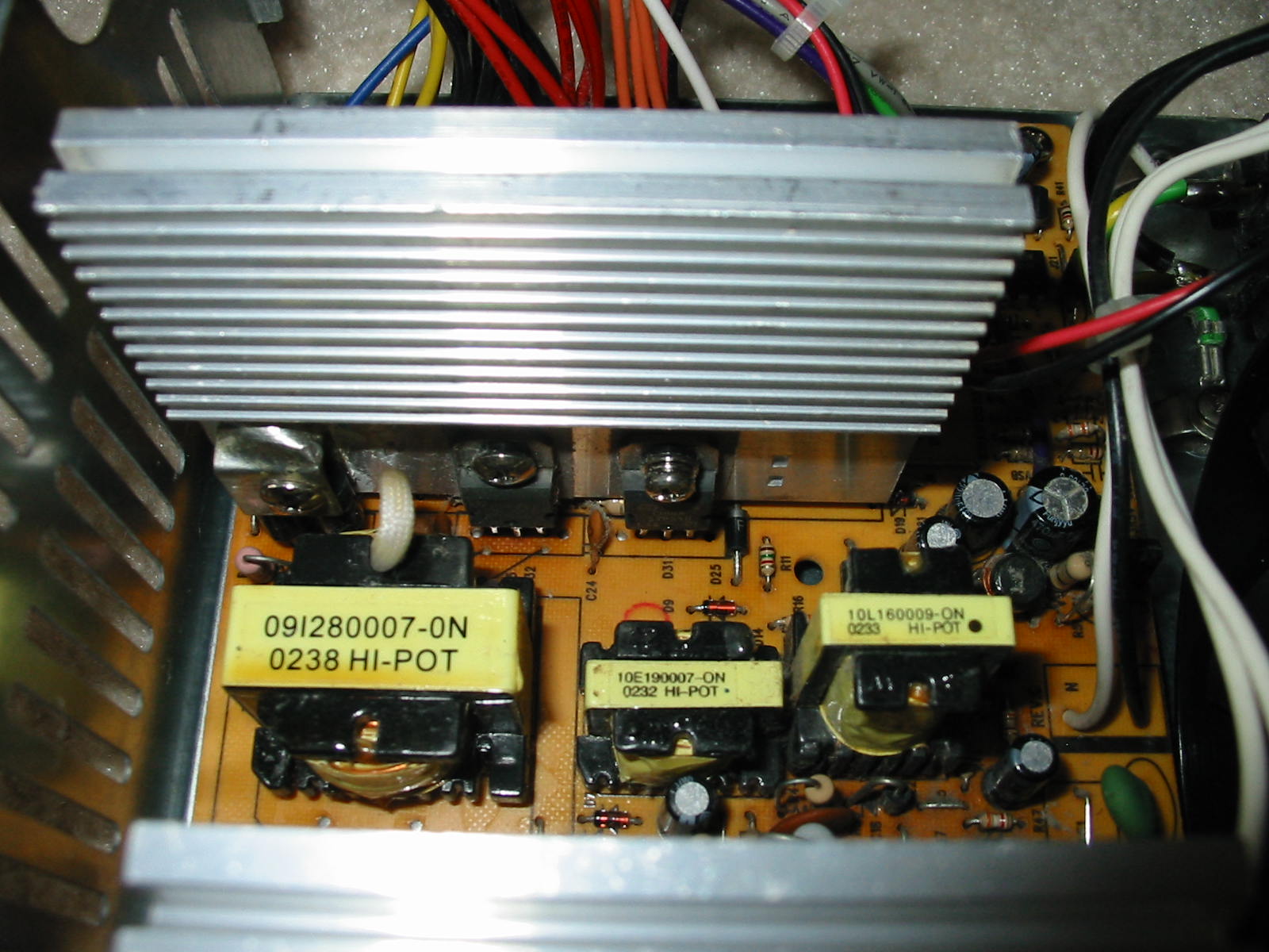
And finally, the guts (or the lack of any, if you will):

Yup, it’s our old friend, the half-bridge.
The heatsinks are fairly okay-sized - for a 200W PSU. Everything else is… well, how to say it nicely? … very undersized. Just look at those transformers! The main transformer is size “28” . That would be an acceptable size for a 19” LCD monitor, not a PC PSU – especially one claiming 320W! The BJT base-drive transformer is the typical small cute stuff in gutless wonder PSUs. I doubt it is a real size “19”. Only the 5VSB traffo is normal size.
The worst part, however, is the 3.3V rail. Keen eyes may have noticed that there are no saturation and filter toroids for the 3.3V rail, thinking that this is perhaps a linear design with a MOSFET. Yet, as you are about to see below, there is no MOSFET for the 3.3V rail, so this is not a linear circuit either.
No, it is much simpler than that. In fact, it’s so simple, it is stupid (it really is! )… the 3.3V rail is derived just the same way as the 5V, 12V, -12V, and -5V rails. In other words, this is a mega group-regulated design, and all of the rails share that same tiny output toroid coil.
My guess would be that the 3.3V regulation is very crappy. I dare not I try this PSU in a computer, though.
Anyways, a more detailed breakdown follows below.
Primary/input side:
Not much to talk about the input filter. It’s been replaced by a bunch of jumpers. :\
Diodes for bridge rectifier appear to be 2A0x – i.e. a standard 2A diodes.
Primary caps are MK (?) 330 uF, 200V, 85C, 22x30 mm. Their real capacity, however, is only 173 uF and 146 uF respectively (with the second one showing almost 2x the ESR of the first cap – about 0.4 Ohms). I suspect these are Fuhjyyu rejects in disguise (since Fuhjyyu does have an “MK” series). But who knows.
Primary switchers for the main PS are a pair of 2SC5763 NPN BJTs, which are weaker than the standard 13007’s we normally get in most gutless wonders.
5VSB has a 2SC5027 NPN BJT.
Secondary/output side:
All output caps are Fuhjyyu TNR. Just saying this so I don’t have to keep re-typing it.
3.3V rail has 2x 10V, 470 uF, 8x12 mm caps. PI coil between them has been bypassed with a jumper. Rectifier is rated for 10A and 45V (an STPS10L45CT). Minimum load resistor on this rail is 15 Ohms.
5V rail also has 2x 10V, 470 uF, 8x12 mm caps and PI coil bypassed with jumpers. Rectifier is rated for 15A and 45V (an STPS1545CT). Load resistor on this rail is 150 Ohms.
12V rail has a single 16V, 470 uF, 8x14 mm cap, though there is an empty spot on the board for a second 8mm cap. PI coil is *sigh* bypassed again. For a rectifier, we get the 3A “diodes-on-a-bracket” treatment. Load resistor on this rail is 470 Ohms.
Both the -12V and -5V rails have only a single 16V, 220 uF, 6.3x11 mm cap each. And both are rectified by a pair of 1.5A (FR153) diodes. Load resistors are 470 Ohms and 150 Ohms for -12V and -5V rails, respectively.
5VSB has a 16V, 220 uF, 6.3x11 mm cap and a 10V, 470 uF, 8x12 mm cap. This time, there was a PI coil installed between them - almost shocking! Output rectifier appears to be either a 1.5A or 2A diode – I couldn’t read the numbers on it. The minimum load resistor is a 68 Ohm (thus pulling about 0.38W).
…
Perhaps that explains the heat marks on the board now. After all, this PSU was powering an old ECS motherboard with a 64W P4 Willamate 1.7 GHz CPU. The motherboard provides power to the CPU from the 5V rail. But the 5V rail on the PSU has only a 15A rectifier – i.e. it can provide a maximum of 75W on the 5V rail. Even worse, the TDP rating of that CPU is average. Its maximum power dissipation rating is about 80W. So on full CPU load, this PSU’s 5V rail was likely getting overloaded. And we are not even counting other devices that could have been using the 5V rail. Interestingly, when I got the PSU, it was quite dusty, so it looks like the PC was in use for a while. How everything has survived is beyond me, though. Even the motherboard caps appear to be okay, despite the skimpy filtering from the PSU. I guess these cheap CWT PSUs really are tougher than they look.
5VSB section:
I’d like to dedicate some detail to the 5VSB circuit, not because it’s something special, but because I had the PSU open and decided to trace the 5VSB circuit anyways.
As stated, the 5VSB main transistor is a 2SC5027 NPN BJT. It’s driven by a C945 (also a NPN BJT). So this is naturally a 2-transistor design (with feedback, as the presence of the optocoupler next to the 5VSB transformer indicates).
Here is a complete schematic of the circuit:
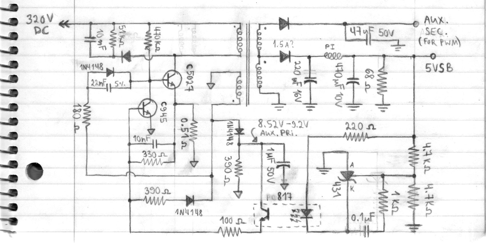
There IS a “critical” capacitor in this 5VSB circuit, though it’s only a 1 uF cap, so I’m thinking the possibility of a very high “killer” 5VSB voltage is unlikely to happen here if this cap was to fail. Nonetheless, I still recommend replacing it if you have one of these “better-built” CWT units that you’d like to save.
That said, I did notice something interesting about the 5VSB on my unit when I powered it up yesterday. With no load, everything appeared normal and the voltage on 5VSB was normal too – about 4.98V. I then put an incandescent car bulb on the 5VSB that loaded it with about 356 mA. The voltage was still normal at 4.92V. However, when I unplugged the PSU (with the bulb still hooked), the 5VSB made a longer and louder-than-normal screeching sound – something that my Turbolink CWT unit does NOT do at all. I’ve seen this before with a cheap Sun Pro –built RaidMax PSU. It’s usually an indication that the output caps on the 5VSB have started to fail. If nothing is done, the 5VSB secondary auxiliary rail can go out of control eventually (when the caps fail), and possibly end up killing the PWM controller or making the PSU do weird things (on the Sun Pro Raidmax, only the current-limiting resistor for the PWM controller was starting to burn out, but the screeching was present whenever a load of more than 50 mA was present on the 5VSB).
With this CWT PSU, the output caps must have “just” started to fail, because when I checked the primary and secondary auxiliary rails from the 5VSB transformer, they appeared to vary within reasonable limits as I loaded the 5VSB (8.5V to 9.2V for the aux. primary, and 11.6V to 12.6V for the aux. secondary).
So just for fun, I changed the 10V, 470 uF Fuhjyyu TNR output capacitor on the 5VSB with a 6.3V, 820 uF Rubycon MFZ (an Xbox 360 motherboard special ). I attached the same incandescent bulb again and repeated the same power ON, power OFF test. This time, the 5VSB no longer did the loud turn-OFF screech noise and the voltage regulation was rock stable at 4.99V (vs. 4.92V before). Yes, I’m sure the higher capacitance of the new cap is helping, but that Fuhjyyu TNR does appear to be developing high ESR - when I charged it with a 9V battery and shorted its terminals, there was no spark at all. Normally, with 470 uF caps charged like that, I can get a small spark (even with general purpose ones).
Here’s a chart that tabulates all of the experiments I did on the 5VSB:
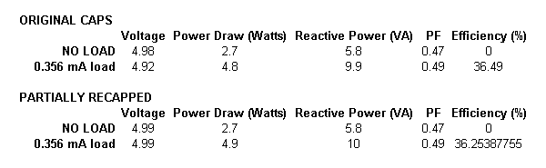
As you can see, the PSU is pulling about 2.7W @ 0.47 PF from the wall even with nothing attached to the 5VSB. Clearly, this is not a very good design! However, it’s not the worst, either. I tested most of my other PSUs, and with the exception of a 250W HiPro, all the 2-transistor PSUs had their 5VSB pull about the same amount of power from the wall with no load. The worst was a Bestec ATX-1956D, pulling over 4W with NO LOAD. Ouch!
Sorry, no other load tests were performed on this PSU. I’m glad I don’t have a scope and load tester, though. Otherwise, I could probably go on.
Okay, I’m finished. Whew!
Let’s start with a case picture:
Perhaps familiar? It’s a power supply that often comes bundled with many cheap cases (though not necessarily under the name of CyberLink). This gem came with a computer I found next to a dumpster. I have another PSU very much like this – a TurboLink (that I haven’t posted pictures of yet). Same case, same QC sticker on the side with all of its various stamps, and of course, similar lack of weight and cables.
Label on the CyberLink:
320W max? Okay, not too overrated, it seems. Let’s see some internal shorts already. The underside of the PCB…
… and we already see some heat marks. Not a good start, I suppose. Soldering is not all too bad, though – certainly better than cheap Sun Pro PSUs and probably many others. Spacing between traces on the primary side is decent.
And finally, the guts (or the lack of any, if you will):
Yup, it’s our old friend, the half-bridge.
The heatsinks are fairly okay-sized - for a 200W PSU. Everything else is… well, how to say it nicely? … very undersized. Just look at those transformers! The main transformer is size “28”
. That would be an acceptable size for a 19” LCD monitor, not a PC PSU – especially one claiming 320W! The BJT base-drive transformer is the typical small cute stuff in gutless wonder PSUs. I doubt it is a real size “19”. Only the 5VSB traffo is normal size.The worst part, however, is the 3.3V rail. Keen eyes may have noticed that there are no saturation and filter toroids for the 3.3V rail, thinking that this is perhaps a linear design with a MOSFET. Yet, as you are about to see below, there is no MOSFET for the 3.3V rail, so this is not a linear circuit either.
No, it is much simpler than that. In fact, it’s so simple, it is stupid (it really is!
)… the 3.3V rail is derived just the same way as the 5V, 12V, -12V, and -5V rails. In other words, this is a mega group-regulated design, and all of the rails share that same tiny output toroid coil.My guess would be that the 3.3V regulation is very crappy. I dare not I try this PSU in a computer, though.
Anyways, a more detailed breakdown follows below.
Primary/input side:
Not much to talk about the input filter. It’s been replaced by a bunch of jumpers. :\
Diodes for bridge rectifier appear to be 2A0x – i.e. a standard 2A diodes.
Primary caps are MK (?) 330 uF, 200V, 85C, 22x30 mm. Their real capacity, however, is only 173 uF and 146 uF respectively
(with the second one showing almost 2x the ESR of the first cap – about 0.4 Ohms). I suspect these are Fuhjyyu rejects in disguise (since Fuhjyyu does have an “MK” series). But who knows.Primary switchers for the main PS are a pair of 2SC5763 NPN BJTs, which are weaker than the standard 13007’s we normally get in most gutless wonders.
5VSB has a 2SC5027 NPN BJT.
Secondary/output side:
All output caps are Fuhjyyu TNR. Just saying this so I don’t have to keep re-typing it.
3.3V rail has 2x 10V, 470 uF, 8x12 mm caps. PI coil between them has been bypassed with a jumper. Rectifier is rated for 10A and 45V (an STPS10L45CT). Minimum load resistor on this rail is 15 Ohms.
5V rail also has 2x 10V, 470 uF, 8x12 mm caps and PI coil bypassed with jumpers. Rectifier is rated for 15A and 45V (an STPS1545CT). Load resistor on this rail is 150 Ohms.
12V rail has a single 16V, 470 uF, 8x14 mm cap, though there is an empty spot on the board for a second 8mm cap. PI coil is *sigh* bypassed again. For a rectifier, we get the 3A “diodes-on-a-bracket” treatment. Load resistor on this rail is 470 Ohms.
Both the -12V and -5V rails have only a single 16V, 220 uF, 6.3x11 mm cap each. And both are rectified by a pair of 1.5A (FR153) diodes. Load resistors are 470 Ohms and 150 Ohms for -12V and -5V rails, respectively.
5VSB has a 16V, 220 uF, 6.3x11 mm cap and a 10V, 470 uF, 8x12 mm cap. This time, there was a PI coil installed between them - almost shocking! Output rectifier appears to be either a 1.5A or 2A diode – I couldn’t read the numbers on it. The minimum load resistor is a 68 Ohm (thus pulling about 0.38W).
…
Perhaps that explains the heat marks on the board now. After all, this PSU was powering an old ECS motherboard with a 64W P4 Willamate 1.7 GHz CPU. The motherboard provides power to the CPU from the 5V rail. But the 5V rail on the PSU has only a 15A rectifier – i.e. it can provide a maximum of 75W on the 5V rail. Even worse, the TDP rating of that CPU is average. Its maximum power dissipation rating is about 80W. So on full CPU load, this PSU’s 5V rail was likely getting overloaded. And we are not even counting other devices that could have been using the 5V rail. Interestingly, when I got the PSU, it was quite dusty, so it looks like the PC was in use for a while. How everything has survived is beyond me, though. Even the motherboard caps appear to be okay, despite the skimpy filtering from the PSU. I guess these cheap CWT PSUs really are tougher than they look.
5VSB section:
I’d like to dedicate some detail to the 5VSB circuit, not because it’s something special, but because I had the PSU open and decided to trace the 5VSB circuit anyways.
As stated, the 5VSB main transistor is a 2SC5027 NPN BJT. It’s driven by a C945 (also a NPN BJT). So this is naturally a 2-transistor design (with feedback, as the presence of the optocoupler next to the 5VSB transformer indicates).
Here is a complete schematic of the circuit:
There IS a “critical” capacitor in this 5VSB circuit, though it’s only a 1 uF cap, so I’m thinking the possibility of a very high “killer” 5VSB voltage is unlikely to happen here if this cap was to fail. Nonetheless, I still recommend replacing it if you have one of these “better-built” CWT units that you’d like to save.
That said, I did notice something interesting about the 5VSB on my unit when I powered it up yesterday. With no load, everything appeared normal and the voltage on 5VSB was normal too – about 4.98V. I then put an incandescent car bulb on the 5VSB that loaded it with about 356 mA. The voltage was still normal at 4.92V. However, when I unplugged the PSU (with the bulb still hooked), the 5VSB made a longer and louder-than-normal screeching sound – something that my Turbolink CWT unit does NOT do at all. I’ve seen this before with a cheap Sun Pro –built RaidMax PSU. It’s usually an indication that the output caps on the 5VSB have started to fail. If nothing is done, the 5VSB secondary auxiliary rail can go out of control eventually (when the caps fail), and possibly end up killing the PWM controller or making the PSU do weird things (on the Sun Pro Raidmax, only the current-limiting resistor for the PWM controller was starting to burn out, but the screeching was present whenever a load of more than 50 mA was present on the 5VSB).
With this CWT PSU, the output caps must have “just” started to fail, because when I checked the primary and secondary auxiliary rails from the 5VSB transformer, they appeared to vary within reasonable limits as I loaded the 5VSB (8.5V to 9.2V for the aux. primary, and 11.6V to 12.6V for the aux. secondary).
So just for fun, I changed the 10V, 470 uF Fuhjyyu TNR output capacitor on the 5VSB with a 6.3V, 820 uF Rubycon MFZ (an Xbox 360 motherboard special
). I attached the same incandescent bulb again and repeated the same power ON, power OFF test. This time, the 5VSB no longer did the loud turn-OFF screech noise and the voltage regulation was rock stable at 4.99V (vs. 4.92V before). Yes, I’m sure the higher capacitance of the new cap is helping, but that Fuhjyyu TNR does appear to be developing high ESR - when I charged it with a 9V battery and shorted its terminals, there was no spark at all. Normally, with 470 uF caps charged like that, I can get a small spark (even with general purpose ones).Here’s a chart that tabulates all of the experiments I did on the 5VSB:
As you can see, the PSU is pulling about 2.7W @ 0.47 PF from the wall even with nothing attached to the 5VSB. Clearly, this is not a very good design! However, it’s not the worst, either. I tested most of my other PSUs, and with the exception of a 250W HiPro, all the 2-transistor PSUs had their 5VSB pull about the same amount of power from the wall with no load. The worst was a Bestec ATX-1956D, pulling over 4W with NO LOAD. Ouch!
Sorry, no other load tests were performed on this PSU. I’m glad I don’t have a scope and load tester, though. Otherwise, I could probably go on.
Okay, I’m finished. Whew!
Attached Files


 .
.


Comment