Fixing a laboratory waterbath

Collapse
X
 
  • Time
  • Show
Clear All
new posts
  • vrasp
    Senior Member
    • Nov 2019
    • 194
    • Canada

    #81
    Re: Fixing a laboratory waterbath

    Hey guys,

    Took a 24h break from this. Now I m back at it.

    I powered on the waterbath, the display lit up for a second then turned off. Moving it around did not make it turn back on. After some measurements, I found that the fuse on the power supply PCB blew. Below is the PCB. The culprit is the fuse above the "15v" text in green. I removed it to double-check, and indeed there is no continuity.


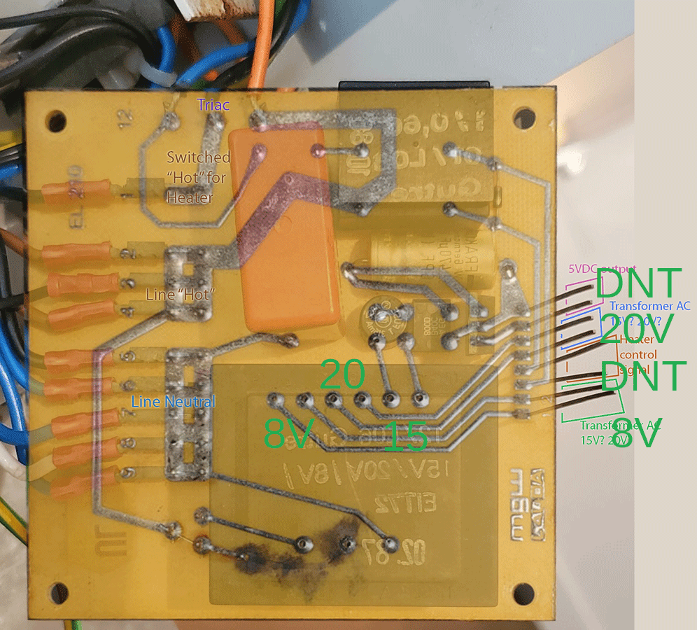
    Do you know why it might have been fine yesterday and blew as soon as I turned on the machine today?

    Is this an indicator that something in the circuit is pulling too much current?

    Can I bypass the fuse? I guessing that's risky.

    Comment

    • eccerr0r
      Solder Sloth
      • Nov 2012
      • 8659
      • USA

      #82
      Re: Fixing a laboratory waterbath

      Never bypass fuses, they are there for a reason. It should have also helped protect that trace that blew in the first place, I still don't know what's the story behind that.

      Supposedly this supply - the 15V -> bridge ->capacitor -> 7805 regulator, though I did not track it carefully, powers the display meter. Having that fuse blow will shut off the meter. Now determining what's causing the overload is another problem, must be something eating a lot of power somewhere on this rail... if it blew right away, this likely is a dead short which is slightly easier to find...

      A "DBT" tester would be helpful here - but not in the regular sense. You should get a 0.5A-1A 12V (6-12W, not a headlamp bulb or brake light, but perhaps a festoon light or side marker) car lamp and use it as the "fuse," so you don't burn too many fuses while searching for the short.

      Comment

      • vrasp
        Senior Member
        • Nov 2019
        • 194
        • Canada

        #83
        Re: Fixing a laboratory waterbath

        Originally posted by eccerr0r
        Never bypass fuses, they are there for a reason. It should have also helped protect that trace that blew in the first place, I still don't know what's the story behind that.

        Supposedly this supply - the 15V -> bridge ->capacitor -> 7805 regulator, though I did not track it carefully, powers the display meter. Having that fuse blow will shut off the meter. Now determining what's causing the overload is another problem, must be something eating a lot of power somewhere on this rail... if it blew right away, this likely is a dead short which is slightly easier to find...

        A "DBT" tester would be helpful here - but not in the regular sense. You should get a 0.5A-1A 12V (6-12W, not a headlamp bulb or brake light, but perhaps a festoon light or side marker) car lamp and use it as the "fuse," so you don't burn too many fuses while searching for the short.
        The trace was my fault (again). The board was touching the metal of the waterbath top.

        Comment

        • petehall347
          Badcaps Legend
          • Jan 2015
          • 4422
          • United Kingdom

          #84
          Re: Fixing a laboratory waterbath

          should be able to trace the short with no power applied .

          Comment

          • redwire
            Badcaps Legend
            • Dec 2010
            • 3900
            • Canada

            #85
            Re: Fixing a laboratory waterbath

            I would check the filter capacitors, they might see higher voltage with the new transformer, or just died from old age. FRAKO are not a brand that lasts.
            With the power off, put on ohmmeter across each one to find where the short-circuit is. The tantalum capacitors could also be a lesser possibility.

            Comment

            • vrasp
              Senior Member
              • Nov 2019
              • 194
              • Canada

              #86
              Re: Fixing a laboratory waterbath

              Petehall347 yes. I ve been checking each pin for anshort to ground. I might put a fuse back on the board and turn everything on without the display board and see if it blows again.


              Originally posted by redwire
              I would check the filter capacitors, they might see higher voltage with the new transformer, or just died from old age. FRAKO are not a brand that lasts.
              With the power off, put on ohmmeter across each one to find where the short-circuit is. The tantalum capacitors could also be a lesser possibility.
              Thank you redwire. I ll try that tomorrow.

              Comment

              • vrasp
                Senior Member
                • Nov 2019
                • 194
                • Canada

                #87
                Re: Fixing a laboratory waterbath

                Looking at the image below, we can see the 2 traces from the top 2 pins go straight down to the bottom right corner then straight to the display board on the botton of the image. This is the same circuit as the fuse. It doesnt seem to go through any capacitor. Does it?


                Now there is something i d like to understand. If indeed it goes straight to the display board, is it safe to assume that the short would be on the display board? Or is that not necessarily the case?
                Last edited by vrasp; 06-13-2021, 09:09 PM.

                Comment

                • eccerr0r
                  Solder Sloth
                  • Nov 2012
                  • 8659
                  • USA

                  #88
                  Re: Fixing a laboratory waterbath

                  disconnect it and see if it goes away?
                  Can't assume, need to check.

                  Comment

                  • vrasp
                    Senior Member
                    • Nov 2019
                    • 194
                    • Canada

                    #89
                    Re: Fixing a laboratory waterbath

                    Originally posted by redwire
                    I would check the filter capacitors, they might see higher voltage with the new transformer, or just died from old age. FRAKO are not a brand that lasts.
                    With the power off, put on ohmmeter across each one to find where the short-circuit is. The tantalum capacitors could also be a lesser possibility.
                    All three capacitors on the green/blue board are working fine. I took them off the board and measured the resistance. It increased slowly as expected.

                    I d like to try power everything on without the display board but I need to get a fuse (or something that would serve as a fuse) before.

                    Comment

                    • petehall347
                      Badcaps Legend
                      • Jan 2015
                      • 4422
                      • United Kingdom

                      #90
                      Re: Fixing a laboratory waterbath

                      best check the AC voltages really .

                      Comment

                      • vrasp
                        Senior Member
                        • Nov 2019
                        • 194
                        • Canada

                        #91
                        Re: Fixing a laboratory waterbath

                        I put a 12v 5w car light I found. I turned the waterbath on and measured 5v DC after the bridge rectifier. I also tried with the display board connected. Even with the display board connected there is still 5v on the output of the bridge rectifier. There doesn't seem to be any issues (aside from the fact that the display still doesn't turn on).


                        By the way, the car light does not turn on. I suppose there is not enough watts going through it to light it up. I suppose if it were broken there wouldnt be continuity. Does that mean the current drawn is very very small?

                        Why did the fuse blow in the first place but now it works? Could be my fault. Maybe I accidentally touched something with my multimeter and shorted it (just a hypothesis).

                        The display still doesn't work though.

                        I measured the voltage on each pin that goes from the green/blue board to the display board (without the display bosrd connected):

                        The pins are on the bottom of this picture. From left to right.


                        Pin 1: 6v
                        Pin 2: 3.6v
                        Pin 3: 11v
                        Pin 4: 6.14v
                        Pin 5: 6.14v
                        Pin 6: 0v
                        Pin 7: 5.25v
                        Pin 8: 0v
                        Pin 9: 0.06v
                        Pin 10: 8.6v
                        Pin 11: 4.2v
                        Pin 12: 1.4v

                        Anything suspect? Pins 9 and 12 maybe. I think 11 is supposed to be 5v since it s coming straight from the bridge rectifier of the PS board.

                        Remember, thise measurements were done with the display board disconnected (in the picture its connected).

                        It wasn't easy to measure. The board is dangling and I try to be super careful. I will double check those voltages tomorrow.
                        Last edited by vrasp; 06-14-2021, 10:03 PM.

                        Comment

                        • eccerr0r
                          Solder Sloth
                          • Nov 2012
                          • 8659
                          • USA

                          #92
                          Re: Fixing a laboratory waterbath

                          You have a very strange problem, it can go from working -> open -> shorted -> working... you'll have to monitor what conditions cause it to go to each state.

                          The lamp should not light if there's no short. However the lamp should allow the 5V to go through like an intact fuse.

                          Comment

                          • vrasp
                            Senior Member
                            • Nov 2019
                            • 194
                            • Canada

                            #93
                            Re: Fixing a laboratory waterbath

                            I have double checked those voltages I listed. They are correct.

                            I have not been able to purposefully recreate the short.

                            I m not sure where to go from here. Maybe I can put some new solder on every solder point of the board.

                            If you have any suggestions let me know.

                            Comment

                            • eccerr0r
                              Solder Sloth
                              • Nov 2012
                              • 8659
                              • USA

                              #94
                              Re: Fixing a laboratory waterbath

                              An intermittent problem - one of the toughest ones to debug. You'll have to go through each board manually, use like a stick or something and carefully poke at items until something causes a reaction.

                              I did this on one of the radios I had... had an FM stereo that didn't produce stereo - AM was ok. I found out if I flexed the board, the FM would work. Not having a schematic, I started poking components and found a coil that was intermittent. I reflowed the solder and boom, FM started working like new once more.

                              Comment

                              • vrasp
                                Senior Member
                                • Nov 2019
                                • 194
                                • Canada

                                #95
                                Re: Fixing a laboratory waterbath

                                Finally was able to get something while poking around!

                                https://files.fm/f/6ce8up82u

                                From this, I would say it's either the pins from the green/blue board that are not well seated or the ones on the display board. What do you think?

                                Comment

                                • vrasp
                                  Senior Member
                                  • Nov 2019
                                  • 194
                                  • Canada

                                  #96
                                  Re: Fixing a laboratory waterbath

                                  I put new solder on the display board joints. That did it!

                                  Now back to the other issues. I think the temperature was stuck to 35.7 celcius. Looking into that.

                                  Comment

                                  • vrasp
                                    Senior Member
                                    • Nov 2019
                                    • 194
                                    • Canada

                                    #97
                                    Re: Fixing a laboratory waterbath

                                    I m still getting some issues with the display. It s sometimes dim or I have to move it slightly. It seems to be caused by a misconnection between the long pins and the metal part inside the white plastic display board connector. I noticed there is some sticky matter on the display board. I cleaned it off but I cant clean it inside the holes of the display connector.

                                    How can I clean this thoroughly and make sure those long pins are in contact with the metal inside the female connection of the display board.

                                    Basically I want to clean the inside of these holes.

                                    Comment

                                    • eccerr0r
                                      Solder Sloth
                                      • Nov 2012
                                      • 8659
                                      • USA

                                      #98
                                      Re: Fixing a laboratory waterbath

                                      As an off-colored joke, yes I think those connectors are tired of being f**ked from behind. I suppose that's why not many people design boards with that kind of connector, not only the manual labor required to assemble them.

                                      That connector between the blue and display board probably is the most stressed from the vibrations, not sure if a mere cleaning is sufficient, you will likely need to get creative to renew those contacts. The similar connections from the display board to the LED board probably don't feel much vibration and thus have persisted.

                                      Comment

                                      • vrasp
                                        Senior Member
                                        • Nov 2019
                                        • 194
                                        • Canada

                                        #99
                                        Re: Fixing a laboratory waterbath

                                        Originally posted by eccerr0r
                                        As an off-colored joke, yes I think those connectors are tired of being f**ked from behind. I suppose that's why not many people design boards with that kind of connector, not only the manual labor required to assemble them.

                                        That connector between the blue and display board probably is the most stressed from the vibrations, not sure if a mere cleaning is sufficient, you will likely need to get creative to renew those contacts. The similar connections from the display board to the LED board probably don't feel much vibration and thus have persisted.
                                        Actually, as I was about to try to figure out the temperature issue, the car light started lighting up and blinking. When I remove the LED board from the display board, it stops. I suppose there is something wrong with the LED board or the connections between the 2.

                                        I thought of wiring the boards that have those pins but its time consuming and requires smaller wires than the ones I have. It also means I wont be able to remove it without desoldering everything if something else goes wrong.

                                        I feel like I m taking one step forward two steps back haha

                                        Comment

                                        • petehall347
                                          Badcaps Legend
                                          • Jan 2015
                                          • 4422
                                          • United Kingdom

                                          #100
                                          Re: Fixing a laboratory waterbath

                                          some people use pencil erasers to clean connector pins .

                                          Comment

                                          Related Topics

                                          Collapse

                                          • ohren
                                            Original Xbox 1.0 PSU: Foxlink FTPS-0002 Rev. B. — 12 V low, 5 V high — transformer?
                                            by ohren
                                            Hello!

                                            I'm looking at an original Xbox PSU: Foxlink ftps-0002 rev. B. The 12 V output is too low, and the 5 V output is too (?) high. Unfortunately I don't have an oscilloscope but only a DMM for diagnosis.

                                            Measured voltages with no load:

                                            After rectifier diodes
                                            12V: 6.17 V
                                            5V: 5.67 V

                                            Secondary transformer pins AC measurement (really don't know if this says anything)
                                            12V: 2-2.5 V
                                            5V: 1.04 V


                                            I also have another (working) Xbox psu from Delta. The same measures there, in order, being: 10.79,...
                                            03-18-2023, 10:33 AM
                                          • mikey5791
                                            Is it possible for transformer substitution?
                                            by mikey5791
                                            Hi all,
                                            Got this local made DC power supply (12/14V) given free as the transformer has melted. There is no marking or indication to identify what type or rating of transformer used.
                                            Fyi,. I had a busted autogate mainboard with transformer with marking 13-0-13 . Is this the 13v dc type transformer?
                                            My questions are
                                            1. How do i test to see if the transformer is in good working condition?
                                            2. Can this transformer (marking 13-0-13) be used to replace the melted transformer on the DC power supply?
                                            Hope you guys understand what i was asking. My intention is...
                                            11-03-2022, 02:11 AM
                                          • dennis_elx33
                                            3PHASE STEP-DOWN Transformer in Check
                                            by dennis_elx33
                                            Hello All,

                                            i would like to post an interesting topic regarding 3-phase stepdown transformer which we suspect to cause an overcurrent (138A) which resulted to power tripped off of the HV power supply (80KV output).


                                            Problem statement: Power tripped Off

                                            Initial Problem: Found 2 IGBT and 2 rectifier diodes shorted (burnt).

                                            Action Done:
                                            1) Replaced the faulty parts with good spare.
                                            2) Measured impedance of the 3phase input lines and found that L2 to L3 has 23.3ohm while other pairs are 51Kohm. This pins will...
                                            12-02-2024, 06:52 AM
                                          • Document Archive
                                            ASUS Transformer T101HA - X5DHD Hybrid (2-in-1) Book Specification for Upgrade or Repair
                                            by Document Archive
                                            This specification for the ASUS Transformer T101HA - X5DHD Hybrid (2-in-1) can be useful for upgrading or repairing a laptop that is not working. As a community we are working through our specifications to add valuable data like the T101HA - X5DHD boardview and T101HA - X5DHD schematic. Our users have donated over 1 million documents which are being added to the site. This page will be updated soon with additional information. Alternatively you can request additional help from our users directly on the relevant badcaps forum. Please note that we offer no warranties that any specification, datasheet,...
                                            09-06-2024, 04:40 PM
                                          • Document Archive
                                            ASUS Transformer T304UA-P71SP-CA Hybrid (2-in-1) Pro Specification for Upgrade or Repair
                                            by Document Archive
                                            This specification for the ASUS Transformer T304UA-P71SP-CA Hybrid (2-in-1) can be useful for upgrading or repairing a laptop that is not working. As a community we are working through our specifications to add valuable data like the T304UA-P71SP-CA boardview and T304UA-P71SP-CA schematic. Our users have donated over 1 million documents which are being added to the site. This page will be updated soon with additional information. Alternatively you can request additional help from our users directly on the relevant badcaps forum. Please note that we offer no warranties that any specification, datasheet,...
                                            09-06-2024, 12:00 PM
                                          • Loading...
                                          • No more items.
                                          Working...