
Hi everyone,
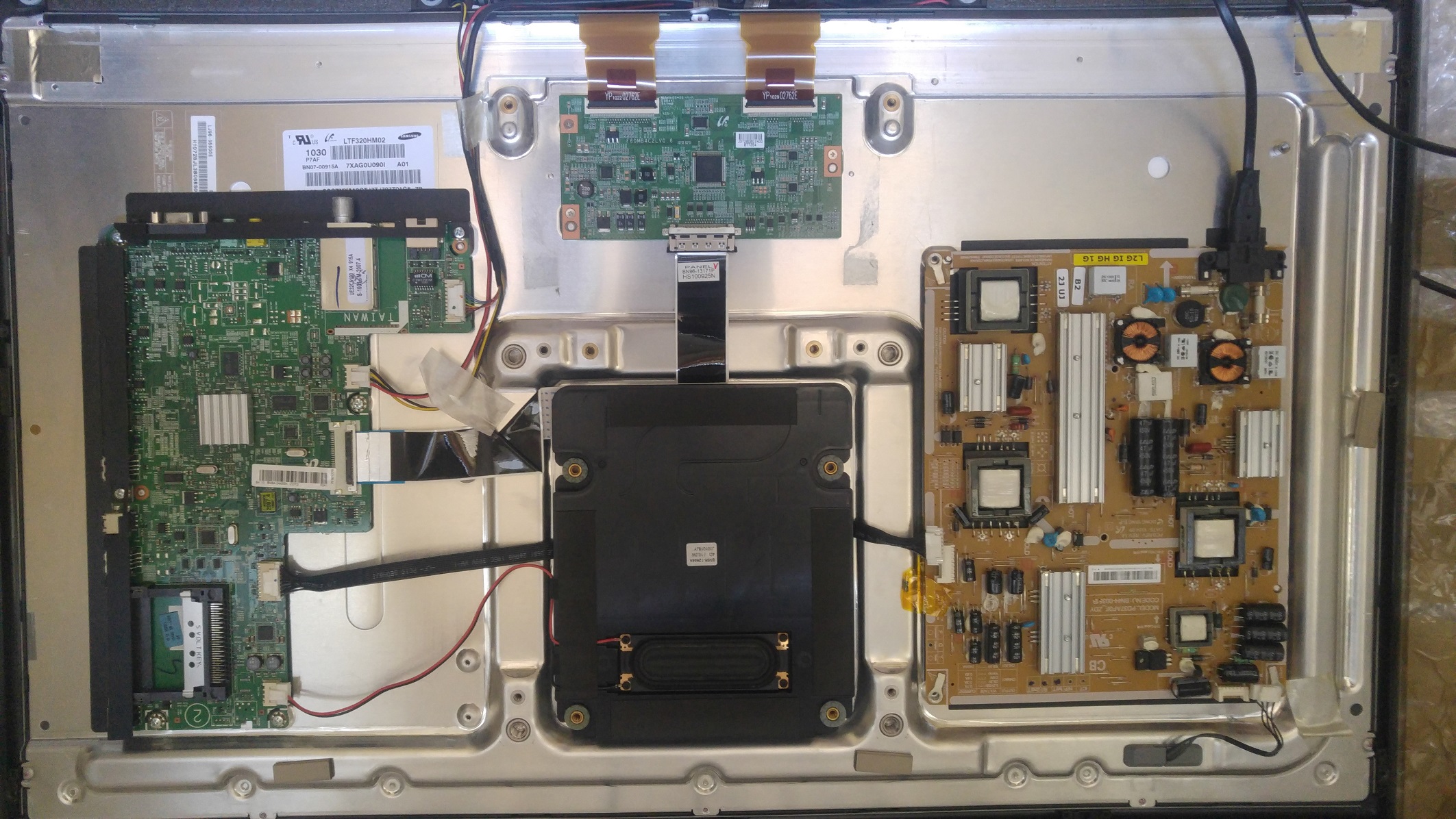
got this TV with no backlight.
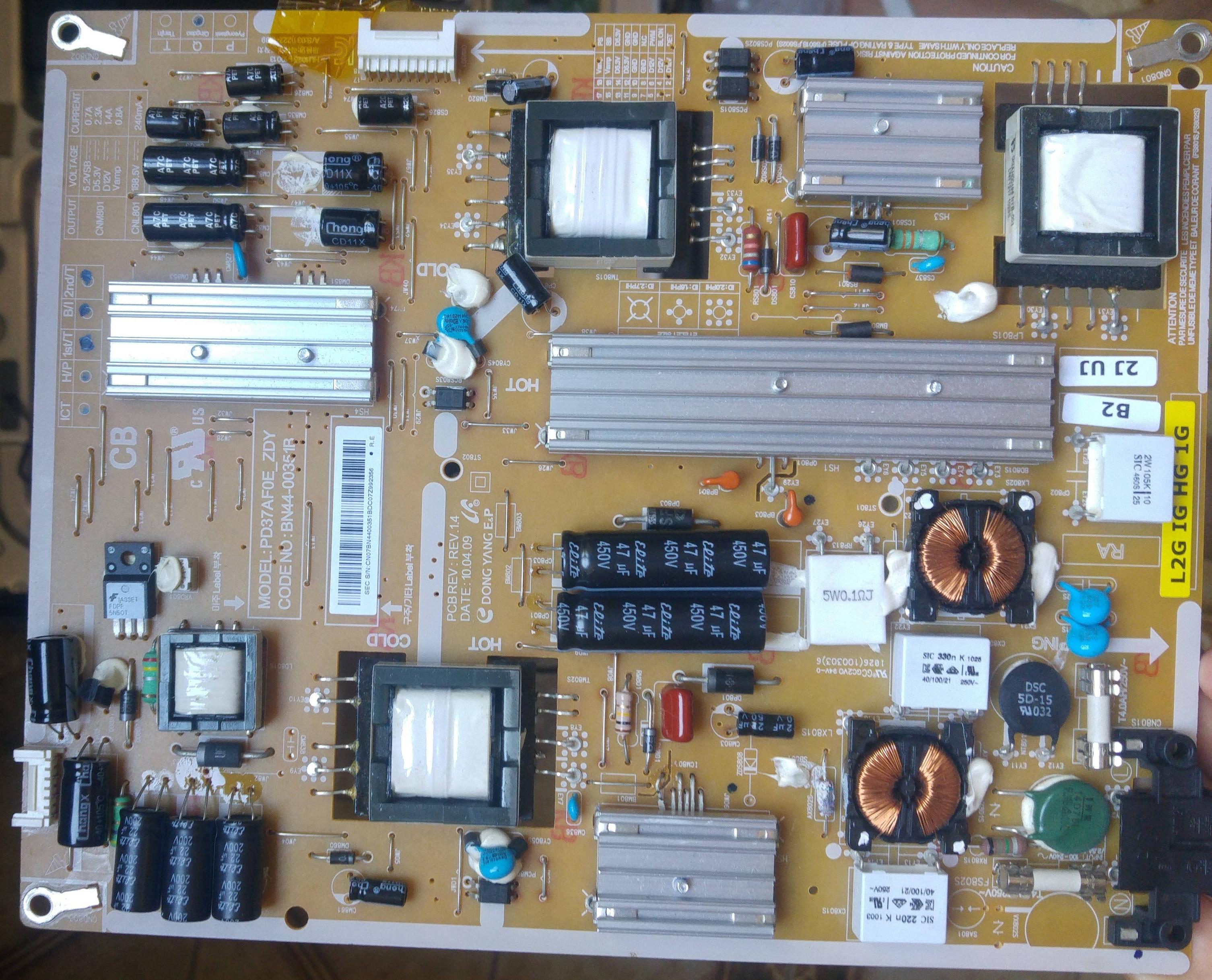
Soldered a 1k resistor between pin 16 and 18 of CNM801 and measured all the voltages.
Seems all ok, but in the drive block output i don't have high voltage for the backlight.
In fact the TV power on correctly, can hear the sound and can see that the panel is working if i put a torch in front of it.
How to troubleshoot the backlight? Thanks
got this TV with no backlight.
Soldered a 1k resistor between pin 16 and 18 of CNM801 and measured all the voltages.
Seems all ok, but in the drive block output i don't have high voltage for the backlight.
In fact the TV power on correctly, can hear the sound and can see that the panel is working if i put a torch in front of it.
How to troubleshoot the backlight? Thanks


Comment