Announcement

Collapse
No announcement yet.

Antec SL350P PSU

Collapse
X
 
  • Filter
  • Time
  • Show
Clear All
new posts

    Antec SL350P PSU

    Hello,

    I decided to recap my SL350P after the computer started to crash very often, and I noticed that some caps on the mainboard were bulging (about this in a later thread). So I opened the PSU also, and it was full of Fuhjyyu's (Antec's favourite brand, it seems), with one capacitor already bloated.

    Here is the list of the capacitors I found and their planned replacements (sorry for the dirty solution of posting an image, it was easier with formatting):


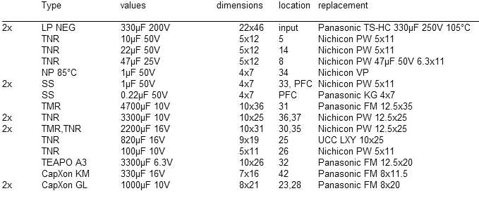
    Most of the capacitors are Fuhjyyu (I wrote only the type), and additionally a Teapo and two Capxons. I would like to replace all of them, just to be sure.

    The two big capacitors will be replaced with Panasonics with a higher temperature and voltage rating.

    The TNRs will be replaced by Nichicon PW series, as well as one TMR because its PW counterpart has anyway better specifications.

    The TMR that bloated (4700uF/10V) will be replaced by a Panasonic FM, as will also the other 6.3/10/16 V capacitors.

    There is one non-polar capacitor, rated for 85°C, whose silkscreen was actually for a polar. I have found a replacement also, but i don't know whether it's better to install a polar, but with 105°C rating.

    The capacitors at PFC positions are in a small PCB that is probably from the PFC circuit; it is installed atop the two input capacitors.

    I want to order from digikey, as they have the best shipping costs (free above 65€).

    Please have a look at this and tell me if there is anything wrong. I am especially unsura about the sizes of some replacements, bigger than the originals. Maybe instead of 10V I could go to 6.3V, or decrease the capacitance a bit? I know nothing about PSU design, so I need to rely on an expert's opinion. Anyway, the bloated 4700uF cap had anyway larger space around, so 2.5 mm more in diameter would cause no problems.

    I will post some pictures later in the day.

    Thanks!

    Dan
    Attached Files

    #2
    Re: Antec SL350P PSU

    I'm not sure but I think you'll need to double-check the ripple and ESR values for those TNR capacitors - the PW series may not be good enough strictly going by the specifications.

    Yes, if there's room on the board, you can probably with larger caps as long as the specifications match or are better.

    Also since you're in Germany, Farnell could be a better choice as it's based in UK as far as I know, so you'll only pay a few euro in shipping costs. They also have a German version of their website: http://de.farnell.com/

    They also have Rubycon and some other series of capacitors that I think are better than Nichicon PW series for a price very close to theirs or better.

    That whole list shouldn't cost more than 15-20 euro, so it would be silly to pay 65 euro to ship a package to you in Germany.

    Comment


      #3
      Antec SL350P PSU - pictures

      Hi,

      I did not find ESR values for neither TMR nor TNR caps (I looked in datasheets for TN and TM which are listed as general purpose). As for the ripple current, it is comparable, maybe better for the PWs.

      With Farnell, for some of the capacitors (usually the best ones) one has to pay a flat rate of 20€ for import from USA, in addition to 5-7€ for shipping. The 65€ I mentioned are for capacitors that will go in 2 PSUs and 2 MBs, shipping would be otherwise 18€.

      Here are some photos:

      general view


      detail middle top


      detail middle bottom


      detail right top


      detail right bottom


      the nonpolar cap


      PFC module (?)
      Attached Files

      Comment


        #4
        Re: Antec SL350P PSU

        Wait, only 330uF input caps? I'd be Replacing them with at least 560uF or higher.
        I love putting bad caps and flat batteries in fire and watching them explode!!

        No wonder it doesn't work! You installed the jumper wires backwards

        Main PC: Core i7 3770K 3.5GHz, Gigabyte GA-Z77M-D3H-MVP, 8GB Kingston HyperX DDR3 1600, 240GB Intel 335 Series SSD, 750GB WD HDD, Sony Optiarc DVD RW, Palit nVidia GTX660 Ti, CoolerMaster N200 Case, Delta DPS-600MB 600W PSU, Hauppauge TV Tuner, Windows 7 Home Premium

        Office PC: HP ProLiant ML150 G3, 2x Xeon E5335 2GHz, 4GB DDR2 RAM, 120GB Intel 530 SSD, 2x 250GB HDD, 2x 450GB 15K SAS HDD in RAID 1, 1x 2TB HDD, nVidia 8400GS, Delta DPS-650BB 650W PSU, Windows 7 Pro

        Comment


          #5
          Re: Antec SL350P PSU

          Pfc boosts the Voltage, so you get the same charge with lower capacity (Q=C*V)

          You SHOULD fan mod the power supply if you want to avoid the pfc circuit getting shorted and possibly damaging your motherboard.

          My experience:
          https://www.badcaps.net/forum/showthread.php?t=8385

          Comment


            #6
            Re: Antec SL350P PSU

            Ah, whoops, I forgot it had APFC.
            I love putting bad caps and flat batteries in fire and watching them explode!!

            No wonder it doesn't work! You installed the jumper wires backwards

            Main PC: Core i7 3770K 3.5GHz, Gigabyte GA-Z77M-D3H-MVP, 8GB Kingston HyperX DDR3 1600, 240GB Intel 335 Series SSD, 750GB WD HDD, Sony Optiarc DVD RW, Palit nVidia GTX660 Ti, CoolerMaster N200 Case, Delta DPS-600MB 600W PSU, Hauppauge TV Tuner, Windows 7 Home Premium

            Office PC: HP ProLiant ML150 G3, 2x Xeon E5335 2GHz, 4GB DDR2 RAM, 120GB Intel 530 SSD, 2x 250GB HDD, 2x 450GB 15K SAS HDD in RAID 1, 1x 2TB HDD, nVidia 8400GS, Delta DPS-650BB 650W PSU, Windows 7 Pro

            Comment


              #7
              Re: Antec SL350P PSU

              After replacing the capacitors, it almost works: it outputs 5.12V in standby, however when I short the green wire to ground it does not output full voltages: something like 7V on the 12V rail, 3-4V on the 5V rail which drop even further when I put a small resistive load (about 45W for a working PSU).

              I power it up using a 100W light bulb in series with it. When I plug it in, the bulb flashes shortly while the capacitors are loading, then the 5Vsb line gets powered. On power up, the fans start to spin (at low speed) and the bulb glows, but not at full power.

              Now the long story:

              After replacing the caps, I (impatiently) plugged it in to see how it works (first mistake). I think now that I might not have cleaned up wery well the solder joints and the solder rests on the PCB. It was silent for a period of a few seconds, while I reached for my DMM to check the standby voltage. Before being able to measure, it made a discreet pop and died. The fuse (8A) was blown, so I replaced it, installed the PCB in the case to make sure it is properly grounded, hooked it up to some fans and a non-working mainboard to have some load (second mistake) and plugged it in. An instant loud pop this time, the NTC thermistor used as inrush limiter exploded, the circuit breaker tripped. The fuse (6.5A this time) was saved

              I decided it's time to start thinking and try to act in a safer manner. I checked the 5Vsb circuit (two-transistor, more about it later), it was OK. Also the rectifying bridge seemed to be intact, and the filter capacitors. I checked the two big input capacitors with the DMM: I confirmed they are able to hold a charge by measuring in diode test mode then quickly reversing the terminals.

              The MOSFETS on the primary side also test good: gate to drain or source shows open circuit, and drain to source shows only the voltage drop of the internal diode connected in parallel. The only faulty component I found was a MOSFET on what I believe it is the active PFC circuit, the add-on card that sits on top of the two input caps and also contains the rectifying bridge (you can see it in the first picture, on the left side).

              This MOSFET is a Toshiba 2SK2996, and it was shorted between gate and drain, while drain-source was open. I tried to find a quick replacements at the stores nearby, and what I found was a 20N60S5. The datasheets are attached. While the replacement has a higher current rating and lower gate-source leak current, the rise time and turn-on time are shorter for the original. This is what I see at at first look, but I have no clue whether this is crucial.

              After replacing the MOSFET, cleaning up well this time of solder and flux, and using a light bulb in series , the standby voltage came right up at the first attempt, after a short flash of the bulb. Some power resistors were already connected on the 12V, 5V and 3.3V rails to make a load slightly above the minimum required by the sticker on the case (as I wrote above, 45W in total), so I powered it up. The bulb started to light continuously, the fans received a short impulse then stopped, and a weak buzzing sound was coming out of the PSU. I did not leave it in this state for too long, but wanted to see what it outputs. I did so by powering it up in short intervals, enough to measure the voltages, which were all below 1V. I removed the load resistors, attempted again a few startups, with the same results. At some point, however, the fans started to run continuously, and the voltages were as I described them in the first paragraph.

              So where is the input power going, and what should I do next? Please keep in mind that I have almost zero knowledge, so what I assume might be complete nonsense. I checked the heatsinks after unplugging and waiting a few minutes (first making sure there is no voltage on them, they are grounded anyways). Only the one with the replaced MOSFET was warm to touch, so probably this is the ditch where all the power goes. Next to it there is a small PCB with an IC on it (pulse-width modulator?) on which I replaced two small electrolitics. Maybe it was overkill, and maybe in the process I damaged some of the circuitry?

              I would be glad to receive some suggestions about what to do next. In the meantime, hoping that in the end the PSU will come to life again (it was functional before I hacked it, save for one slightly bloated capacitor), I decided to apply the now-famous everell DM311 mod, so I already ordered the parts. The standby circuit is the same as in this post.
              Attached Files

              Comment


                #8
                Re: Antec SL350P PSU

                Fault in APFC section. Check boost voltages on mains caps. Possible bad APFC controller IC.

                Better pic of APFC section?

                Check the poly (green) caps in the APFC for discoloration/cracks/burns.

                2SK2996: available on eBay
                Last edited by Toasty; 10-11-2011, 10:02 AM.
                veritas odium parit

                Comment


                  #9
                  Re: Antec SL350P PSU

                  Here are pictures of the APFC circuit. I hope the picture quality is good enough (at least my poor soldering skills are now showing well). The heatsink on which transistor Q102 and diode D103 are installed was removed for the pictures. Later I will post also a schematic of the circuit.

                  The green caps seem to be OK, I would have to remove them for better visual inspection. I am thinking to replace the two yellow capacitors next to the electrolytics: the tantalum(?) next to the IC and the film capacitor that filters the white connector, because they may have been too close to my soldering gun when replacing the electrolytics. On the other hand, I am afraid that I would do even more damage.

                  A silly question, but just to make sure I am on the right path: the mains caps are the big ones, in my case 330uF/250V, right? I did try to measure the voltage on them, but it turned out that my probe was at a wrong spot in the circuit, so what I measured was nonsense. When I realized, the PSU was already taken apart for photos and did not have time to reassemble it. BTW, while testing, should I put back the old Fuhjyyu 330uF/200V caps, to protect my precious Pannies?

                  Sorry for my slow feedback, I only have time in the evenings to work on this, next to other commitments... add to this the time-zone difference. Nevertheless, I hope we will be able to add some knowledge to the forum
                  Attached Files

                  Comment


                    #10
                    Re: Antec SL350P PSU

                    What's the voltage going to the APFC board from the red wire coming from the middle of the supply? Does it change (rise?) when you jumper it to on?

                    Remember that this is a HOT side voltage and could hurt you if you cross the mains while testing. Voltage on this side should be read with respect to negative (-) at the bridge rectifier, -not- from the output side negative (-).

                    APFC boost on the red-black combo coming from the APFC board (Should go right across the mains caps) could be as high as 380v, so be -VERY- careful when measuring that.

                    Leave the Pannies in place.
                    veritas odium parit

                    Comment


                      #11
                      Re: Antec SL350P PSU

                      You might want to remove and check R109 too. They are low ohm resistors and blow easily and in your case it looks like something has gone on under that heat shrink in pic3. It will be less than 1ohm. The one next to it is a 0.15ohm 3W check that too. Another bit that blows is the 2A ultra fast rectifying diode buried in there somewhere. UF2007 or similar, they go short. I'm working on an AR300 at the mo and all these parts have blown along with the fuse, mosfets etc etc.

                      Comment


                        #12
                        Re: Antec SL350P PSU

                        I measured the voltage between red and black wires: 305V in standby, 95V when the PSU is switched on. Before this I replaced the two caps I mentioned above, plus the 1uF electrolytic.

                        I checked earlier the R109-R110 (parallel) while soldered on the PCB and found something like 0.2 Ohm. Also the diode D102 buried under the toroidal coil tested OK AFAIR, also soldered but with D103 removed. I will check them also when removed, but I will have to leave this for tomorrow.

                        Comment


                          #13
                          Re: Antec SL350P PSU

                          I'm figuring your mains voltage is 215v?

                          The 305v looks correct for standby, the 95 does not and possibly indicates either the replacement FET is not working or the APFC chip is bad, or both.

                          Need the voltage I asked for:
                          "What's the voltage going to the APFC board from the red wire coming from the middle of the supply? Does it change (rise?) when you jumper it to on? "

                          It is the wire going to the small white connector on the APFC board, at the end of the heatsink.

                          Toast
                          veritas odium parit

                          Comment


                            #14
                            Re: Antec SL350P PSU

                            Here is a schematic I drew, with the APFC section in the lower half of the image. The mains should be at 230V, I did not measure but this should be the standard here. I will look for a correct MOSFET for replacement.

                            Sorry, Toasty, I misread your post. I will measure the voltage when I get back home.
                            Attached Files
                            Last edited by amartolos; 10-13-2011, 05:07 AM. Reason: minor spelling corrections

                            Comment


                              #15
                              Re: Antec SL350P PSU

                              Power supplies with APFC won't like the series lightbulb trick. If the bulb only glows weakly (no shorts anywhere) try plugging it straight in and see if all voltages come up.

                              Alternatively, you can bypass the whole active PFC section, by temporarily soldering a bridge rectifier to the primary capacitor. Then wire the AC input cord to this bridge rectifier. You can use the series lightbulb here (not only you can, it's recommended that you do). This way you can find out if the power supply itself is alright.
                              Originally posted by PeteS in CA
                              Remember that by the time consequences of a short-sighted decision are experienced, the idiot who made the bad decision may have already been promoted or moved on to a better job at another company.
                              A working TV? How boring!

                              Comment


                                #16
                                Re: Antec SL350P PSU

                                Hmmm, what is weakly? I would say it glows like a 40W bulb plugged normally. Maybe I can measure later the actual current going through it.

                                I also thought about bypassing the PFC section. Would it be easier if I just disconnect the big inductor (L102 in the schematic) and possibly the wire going to CON101? I don't have a rectifier at hand.

                                Comment


                                  #17
                                  Re: Antec SL350P PSU

                                  Well, the power supply already has a rectifier, before the PFC stage... So you could pull 2 wires from that and connect to the primary cap. And yes, do remove the APFC inductor when you test it like that.
                                  Originally posted by PeteS in CA
                                  Remember that by the time consequences of a short-sighted decision are experienced, the idiot who made the bad decision may have already been promoted or moved on to a better job at another company.
                                  A working TV? How boring!

                                  Comment


                                    #18
                                    Re: Antec SL350P PSU

                                    ...and make sure you get the polarity right, it's not AC after the rectifier but (high voltage) DC.

                                    Comment


                                      #19
                                      Re: Antec SL350P PSU

                                      I didn't have yet time to try to bypass the APFC circuit. While soldering and desoldering I found out that the resistor R107 has a value of about 1.8 kOhm, while the color bands should indicate something between 100-200 Ohm, if I don't mistakenly see the first and third band as brown (or are they red?) Please have a look and tell me, it is the power resistor mounted vertical to the PCB, at the left of the coil in picture 3, with grey background color.

                                      The other two power resistor showed values of about 0.1 Ohm, and also the diodes D102 and D104 tested good.

                                      I also measured the voltage going to CON101, it is 0 V in standby and 18 V when powered up.

                                      Next report will be probably tomorrow.
                                      Last edited by amartolos; 10-13-2011, 01:00 PM. Reason: the other left

                                      Comment


                                        #20
                                        Re: Antec SL350P PSU

                                        red-grey-red = 2.8k ohms -> not a standard value
                                        brown-grey-brown = 180 ohms -> a standard value

                                        The resistor is bad.

                                        18v on the red wire means Vcc to the board is good. The correct power is coming to the board to run the PFC chip.

                                        Replace the resistor and give it a shot.

                                        Toast
                                        veritas odium parit

                                        Comment

                                        Working...
                                        X