Announcement

Collapse
No announcement yet.

Ammeter Setup not Behaving

Collapse
X
 
  • Filter
  • Time
  • Show
Clear All
new posts

    Ammeter Setup not Behaving

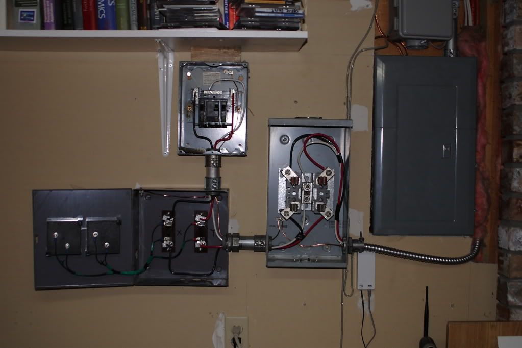
    For those who did not follow the other thread, I installed a 240V 40A branch panel in the house and for monitoring purposes I also installed a standard 200A KWH meter and two 50A 75mv shunt driven ammeters.


    For testing I'm using a 120v 1500w space heater which according to the formula should mean a 12.5A load. The problem is that the (appropriate) ammeter isn't reading anything at all. Even adding a 1200w toaster oven didn't budge the needle. I ended up having to drag out a vacuum cleaner to see the needle nudge up one amp during startup.

    Not sure if the shunt configuration is not correct or I'm not properly load testing the system. With the racks and home theatere not yet installed I don't have half a dozen servers to load the system. Only random appliances around the house.
    Find Nedry!


    Check the Vending machines!!

    <----Computer says I need more beer.

    #2
    Re: Ammeter Setup not Behaving

    Are the shunts made for the Amp-meter? Do you have the spec for the Amp meter that should tell you what kind/value of shunts can be used with the meter. 75mV @50A is not even enough to bias on the Diode. Spec of the meters?
    Never stop learning
    Basic LCD TV and Monitor troubleshooting guides.
    http://www.badcaps.net/forum/showthr...956#post305956

    Voltage Regulator (LDO) testing:
    http://www.badcaps.net/forum/showthr...999#post300999

    Inverter testing using old CFL:
    http://www.badcaps.net/forum/showthr...er+testing+cfl

    Tear down pictures : Hit the ">" Show Albums and stories" on the left side
    http://s807.photobucket.com/user/budm/library/

    TV Factory reset codes listing:
    http://www.badcaps.net/forum/showthread.php?t=24809

    Comment


      #3
      Re: Ammeter Setup not Behaving

      Specs for the ammeters said that they required the use of 50A 75mv shunts which had to be ordered separately but only cost a few dollars more.

      The ammeters came from here.

      The shunts came from here.
      Find Nedry!


      Check the Vending machines!!

      <----Computer says I need more beer.

      Comment


        #4
        Re: Ammeter Setup not Behaving

        The spec of the shunt is confusing: Is it 200A or 50A rating?
        Description

        Specifications:
        This is a bid of a 200A, 75mV DC current shunt.
        Ideal for use with:Use for DC digital Amp Meter.
        Use for Analog Amp Meter.
        Color: Silver
        Item size: 115*24*17mm
         
        Package included:

        1 x 50A 75mV DC current shunt
        Last edited by budm; 01-23-2013, 11:25 PM.
        Never stop learning
        Basic LCD TV and Monitor troubleshooting guides.
        http://www.badcaps.net/forum/showthr...956#post305956

        Voltage Regulator (LDO) testing:
        http://www.badcaps.net/forum/showthr...999#post300999

        Inverter testing using old CFL:
        http://www.badcaps.net/forum/showthr...er+testing+cfl

        Tear down pictures : Hit the ">" Show Albums and stories" on the left side
        http://s807.photobucket.com/user/budm/library/

        TV Factory reset codes listing:
        http://www.badcaps.net/forum/showthread.php?t=24809

        Comment


          #5
          Re: Ammeter Setup not Behaving

          It's 50A. You can ebay search the 200A shunt and you can see the difference. There's a few sellers using the same description template and they all have the same error.
          Find Nedry!


          Check the Vending machines!!

          <----Computer says I need more beer.

          Comment


            #6
            Re: Ammeter Setup not Behaving

            Do you have any signal generator that can put out 60Hz? You can use that to simulate the 75mV R.M.S. (211.5 V P-P) AC to feed the meter and see if it will display full scale.
            You can also set you DMM to AC mV scale and take voltage reading across the shunt to see if it is the correct shunt.
            25A = 37.5mV
            12.5A = 18.75mV
            6.25A = 9.375mV
            Last edited by budm; 01-24-2013, 01:32 AM.
            Never stop learning
            Basic LCD TV and Monitor troubleshooting guides.
            http://www.badcaps.net/forum/showthr...956#post305956

            Voltage Regulator (LDO) testing:
            http://www.badcaps.net/forum/showthr...999#post300999

            Inverter testing using old CFL:
            http://www.badcaps.net/forum/showthr...er+testing+cfl

            Tear down pictures : Hit the ">" Show Albums and stories" on the left side
            http://s807.photobucket.com/user/budm/library/

            TV Factory reset codes listing:
            http://www.badcaps.net/forum/showthread.php?t=24809

            Comment


              #7
              Re: Ammeter Setup not Behaving

              mV shunts are for metering DC current, or AC current if you have electronics (op-amps) to rectify.

              The panel meters need a current transformer with burden resistor, feeding them. CT's can generate several volts since they are constant-current devices and this overcomes the voltage drop in the panel meter's (internal) diode rectifier.

              I drew a schematic of what possibly is going on. In simple terms, I would go with CT's.
              Attached Files

              Comment


                #8
                Re: Ammeter Setup not Behaving

                I may have some Taewhatrans TS-10L current transformers available. Whole box of 80 at home, but I've got a few here too. They've got a 3000:1 ratio and can do up to 7V output (internal zener clamp prevents higher.)
                Please do not PM me with questions! Questions via PM will not be answered. Post on the forums instead!
                For service manual, schematic, boardview (board view), datasheet, cad - use our search.

                Comment


                  #9
                  Re: Ammeter Setup not Behaving

                  Are they "wire up and you're ready" things? I opted out of buying them originally because I could find no mention that they were what I required for the meters or that they were compatible.
                  Find Nedry!


                  Check the Vending machines!!

                  <----Computer says I need more beer.

                  Comment


                    #10
                    Re: Ammeter Setup not Behaving

                    You need a resistor to set the scale factor and they output AC.
                    Please do not PM me with questions! Questions via PM will not be answered. Post on the forums instead!
                    For service manual, schematic, boardview (board view), datasheet, cad - use our search.

                    Comment


                      #11
                      Re: Ammeter Setup not Behaving

                      At only 75mV full scale at 50A, that is not enough to bias on the rectifier diode (Typical Diode has Vf of about .6V (600mV), you need at least 1.2V to turn on two Diodes in bridge rectifier. You are better off using CT setup.
                      I do not see how they can be selling the meter like that to be used with 75mV/50A shunt without active electronics to drive the meter. I still like tosee what happen if you feed the meter with signal generator to find out what the sensitivity is.
                      Last edited by budm; 01-24-2013, 11:08 AM.
                      Never stop learning
                      Basic LCD TV and Monitor troubleshooting guides.
                      http://www.badcaps.net/forum/showthr...956#post305956

                      Voltage Regulator (LDO) testing:
                      http://www.badcaps.net/forum/showthr...999#post300999

                      Inverter testing using old CFL:
                      http://www.badcaps.net/forum/showthr...er+testing+cfl

                      Tear down pictures : Hit the ">" Show Albums and stories" on the left side
                      http://s807.photobucket.com/user/budm/library/

                      TV Factory reset codes listing:
                      http://www.badcaps.net/forum/showthread.php?t=24809

                      Comment


                        #12
                        Re: Ammeter Setup not Behaving

                        I just moved and this was part of setting the workshop up. The signal generator is currently buried in a storage nook. At this point it's too late for me to redo the system with CT's so I'll have to accomidate for an op-amp rectification.
                        Find Nedry!


                        Check the Vending machines!!

                        <----Computer says I need more beer.

                        Comment


                          #13
                          Re: Ammeter Setup not Behaving

                          This is dangerous but have you tried measuring the voltage across the shunts with a DMM?

                          Could you get a 75 mV AC source to see if the meter actually works (low voltage transformer plus a resistor divider, and use a DMM as a measurement standard)? Though it may be right that it has diodes but I'd give it benefit of the doubt and it could be permanent magnetless meter and thus able to measure AC directly... If it's not, it should go right back into the mail for a refund...

                          Comment


                            #14
                            Re: Ammeter Setup not Behaving

                            All of my bench tools and power supplies are still in storage from a move last month. The most accessible thing I got besides my DMM is my oscilloscope. :/

                            If reading from one side of the shunt to the other side you only see a 0.1v voltage. regardless of load. I do have a more accurate DMM somewhere but I think it is packed away too.
                            Find Nedry!


                            Check the Vending machines!!

                            <----Computer says I need more beer.

                            Comment


                              #15
                              Re: Ammeter Setup not Behaving

                              Analog meters has their best accuracy at 70% of their scale.

                              The house hold power are not capable to even feed correctly those meters.

                              Comment


                                #16
                                Re: Ammeter Setup not Behaving

                                The fixed 0.1V seems kind of wrong, you should see a different voltage across the shunt depending on load (V=IR. If R is constant, V is dependent on I. If it was 75mV = 50A * R, R is 1.5 milliohms!). The scope should be able to detect an AC voltage though it would be fairly low, depending on the amplifiers on the scope may barely register it. If you apply a 10 amp 1200W load assuming 120VAC RMS, you'd get 15 millivolts. On my analog scope, this is only one and a half divisions on the 0.01 scale, which is the lowest it will go.)

                                Warning: Using the scope for this is VERY dangerous as many scope's GND tends not to be isolated!!!

                                Comment


                                  #17
                                  Re: Ammeter Setup not Behaving

                                  h
                                  You can also set you DMM to AC mV scale and take voltage reading across the shunt to see if it is the correct shunt.

                                  12.5A = 18.75mV
                                  Pulled apart my boxes to find my tools.
                                  Tested the shunts both with and without a load and yes, 12.5A load = 18.75mv across the shunt so we know the shunt is behaving and it's the correct one.

                                  However you're telling me that because the ammeter lacks rectification the shunt will not work with it and instead I need a current transformer instead. What exactly should I be looking for? Ebay's got a heck of a selection. Something like this? What should I be looking for?
                                  Last edited by pentium; 01-26-2013, 06:00 PM.
                                  Find Nedry!


                                  Check the Vending machines!!

                                  <----Computer says I need more beer.

                                  Comment


                                    #18
                                    Re: Ammeter Setup not Behaving

                                    Is the meter easy to pull apart without damaging it? Will you be returning these as "not as described"?

                                    I'm still curious as to how the seller thought this should work...is there any presence of a permanent magnetic field on the meter? Maybe the meter is supposed to be a DC ammeter and they misadvertised as AC?

                                    As for the current transformer you'll need to figure out what you want as the readout first...

                                    Comment


                                      #19
                                      Re: Ammeter Setup not Behaving

                                      The ammeters are screwed together with four screws, one of which is covered by a warranty sticker. I topen the ammeter I commit to keeping it.
                                      Find Nedry!


                                      Check the Vending machines!!

                                      <----Computer says I need more beer.

                                      Comment


                                        #20
                                        Re: Ammeter Setup not Behaving

                                        I did some research, because when I worked in substations there are dozens of these meters and I never really paid attention to them... except when they read zero and it all hits the fan...

                                        The seller has an AC panel meter mixed with a DC shunt- together they will not work.

                                        The panel meter is a typical DIN 96mm used in the electrical utility industry, which has many standards to keep things compatible, so real specs (ohms, volts, amps) you will not find.
                                        From your pic, the symbols on the faceplate bottom left tell you the beast is: Moving Iron type, Accuracy Class 1.5 to DIN43780, vertical mount, dielectric strength 2.5kV AC
                                        Moving-iron meters work with AC or DC and I'm wrong about it needing rectifier diodes (moving coil meters need these)

                                        The standard to drive these is a 5A CT, although some meters are for 1A CT's. I'm not sure, your meter looks like a 50A scale one with overload room to 100A. I would try hook it up to a (split-core) 50/5A CT. In other words 50A gives 5A to the meter. A 100A CT with two turns feeding it, could also work.

                                        I'm not sure about the burden resistor. If it's in the meter, then no prob. - but without it it is easy to peg the meter playing around. Take an ohmeter reading on the meter (sans shunt), figure what makes it read full scale if you can.

                                        Comment

                                        Working...
                                        X