Announcement

Collapse
No announcement yet.

Ammeter Setup not Behaving

Collapse
X
 
  • Filter
  • Time
  • Show
Clear All
new posts

    #21
    Re: Ammeter Setup not Behaving

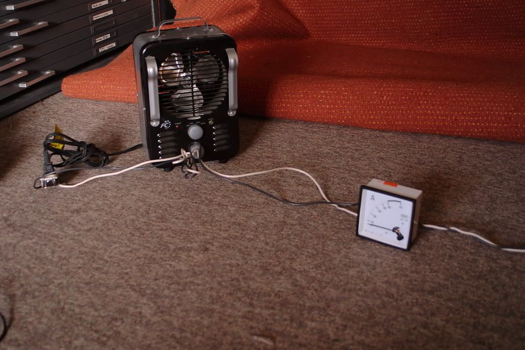
    Yeah, my meter is scaled up to 50A with overload to 100. If you recommend a 50/5A CT those are pretty easy to secure on ebay for about $15 each thankfully.

    As for the resistor I poked at the meter terminals (with the shunt disconnected) and a readong of 0.5 ohms means there shouldn't be anything in there.
    I don't have anything variable enough in the house to peg the scale. My bench supply can deliver the voltage but only 3A max. Even if I turn off current limiting and even slightly turn up the voltage the current draw almost immediately pegs the output limit of the supply. I suspect too that this expects 5A.
    Last edited by pentium; 01-28-2013, 02:05 PM.
    Find Nedry!


    Check the Vending machines!!

    <----Computer says I need more beer.

    Comment


      #22
      Re: Ammeter Setup not Behaving

      I still have some current clamps available.
      Please do not PM me with questions! Questions via PM will not be answered. Post on the forums instead!
      For service manual, schematic, boardview (board view), datasheet, cad - use our search.

      Comment


        #23
        Re: Ammeter Setup not Behaving

        0.5 Ohms does not sound right.
        Never stop learning
        Basic LCD TV and Monitor troubleshooting guides.
        http://www.badcaps.net/forum/showthr...956#post305956

        Voltage Regulator (LDO) testing:
        http://www.badcaps.net/forum/showthr...999#post300999

        Inverter testing using old CFL:
        http://www.badcaps.net/forum/showthr...er+testing+cfl

        Tear down pictures : Hit the ">" Show Albums and stories" on the left side
        http://s807.photobucket.com/user/budm/library/

        TV Factory reset codes listing:
        http://www.badcaps.net/forum/showthread.php?t=24809

        Comment


          #24
          Re: Ammeter Setup not Behaving

          Originally posted by tom66 View Post
          I still have some current clamps available.
          If you can beat $30 shipped for two I'm interested.

          0.5 Ohms does not sound right.
          If they are duds I can still replace them warranty.
          Find Nedry!


          Check the Vending machines!!

          <----Computer says I need more beer.

          Comment


            #25
            Re: Ammeter Setup not Behaving

            Yep. Back to this old thing again. :/

            So I removed the shunts and purchased two 50/5 current transformers along with some more wire to make up for the moving around of things in the cabinet. I used a brass bar to pass through the CT.


            Installation instructions (IS it correct? Most CT's just allow the line to pass through, plus the burden resistor) and another indecipherable piece of chinese.


            Save for the above change mentioned above (no single wind around the CT) the setup now looks like this:


            Again with just the space heater plugged in the CT outputs 0.67v of power.....and the needle doesn't move because if there's diodes in there it's only getting half the voltage it needs to activate the bridge. At this point here I'm sure either my issue is the lack of that single wind around the CT (fixable) or the lack of a burden resistor (what that chinese chart was for?)
            Last edited by pentium; 02-16-2013, 03:05 PM.
            Find Nedry!


            Check the Vending machines!!

            <----Computer says I need more beer.

            Comment


              #26
              Re: Ammeter Setup not Behaving

              That's because you need an AC meter which has zero diode drop.
              Please do not PM me with questions! Questions via PM will not be answered. Post on the forums instead!
              For service manual, schematic, boardview (board view), datasheet, cad - use our search.

              Comment


                #27
                Re: Ammeter Setup not Behaving

                Originally posted by tom66 View Post
                That's because you need an AC meter which has zero diode drop.
                Originally posted by redwire View Post
                From your pic, the symbols on the faceplate bottom left tell you the beast is: Moving Iron type, Accuracy Class 1.5 to DIN43780, vertical mount, dielectric strength 2.5kV AC
                Moving-iron meters work with AC or DC and I'm wrong about it needing rectifier diodes (moving coil meters need these)
                I'm voiding my warranty to get a point across.


                There you have it. No diodes. Just a copper wire that does a few turns around the needle base.

                Anyways I went and redid the CT's with the single wind as the instructions showed so now they are installed as told from China.


                Not pretty but I'm not going for looks. Result is the needle moves but still nowhere near enough for the load. Perhaps the lack of a burden resistor is the issue?
                Last edited by pentium; 02-16-2013, 05:12 PM.
                Find Nedry!


                Check the Vending machines!!

                <----Computer says I need more beer.

                Comment


                  #28
                  Re: Ammeter Setup not Behaving

                  "Result is the needle moves but still nowhere near enough for the load."

                  Try this do not use the shut that came with the unit and just loop the the wire instead and see if that make any different

                  If that is the case then put one more loop through it and see if you get any closer to the right value

                  you might need more than one loop it might be three if there is room
                  Last edited by sam_sam_sam; 02-16-2013, 06:05 PM.

                  Comment


                    #29
                    Re: Ammeter Setup not Behaving

                    Originally posted by sam_sam_sam View Post
                    "Result is the needle moves but still nowhere near enough for the load."

                    Try this do not use the shut that came with the unit and just loop the the wire instead and see if that make any different

                    If that is the case then put one more loop through it and see if you get any closer to the right value

                    you might need more than one loop it might be three if there is room
                    Perhaps you could draw this out for me? Here's essentially how it's setup right now:


                    I'll be honest in that I'm getting super frustrated on this and keep getting told three different solutions, one of which constantly being "you should be using part X instead", only to find that doesn't work either.
                    Find Nedry!


                    Check the Vending machines!!

                    <----Computer says I need more beer.

                    Comment


                      #30
                      Re: Ammeter Setup not Behaving

                      Originally posted by pentium View Post
                      Perhaps you could draw this out for me? Here's essentially how it's setup right now:


                      I'll be honest in that I'm getting super frustrated on this and keep getting told three different solutions, one of which constantly being "you should be using part X instead", only to find that doesn't work either.
                      You aren't allowing all the field around your wire to pass thru the window of the CT.

                      Eliminate that bussbar and either loop your #4 or #6 around the core, or pass it straight thru, depending on the sensitivity required.

                      Your meter is fine. Where the heck did everyone get the idea that there's a diode in there?!

                      The low resistance of the meter is fine. What you can do is put a regular DMM, set to current, in series with the CT and meter. The reading on the DMM should agree with that on the panel meter.

                      Hope it helps...
                      "pokemon go... to hell!"

                      EOL it...
                      Originally posted by shango066
                      All style and no substance.
                      Originally posted by smashstuff30
                      guilty,guilty,guilty,guilty!
                      guilty of being cheap-made!

                      Comment


                        #31
                        Re: Ammeter Setup not Behaving

                        " Where the heck did everyone get the idea that there's a diode in there?!" Well we have no idea what is inside the meter that he bought, we are trying to find how the hell the seller is selling this meter and the shunt to use with the meter, so far it does not work as advertised and can see what is really inside this meter. I doubt that at this point if the meter is actually 50A/75mV full scale.
                        Never stop learning
                        Basic LCD TV and Monitor troubleshooting guides.
                        http://www.badcaps.net/forum/showthr...956#post305956

                        Voltage Regulator (LDO) testing:
                        http://www.badcaps.net/forum/showthr...999#post300999

                        Inverter testing using old CFL:
                        http://www.badcaps.net/forum/showthr...er+testing+cfl

                        Tear down pictures : Hit the ">" Show Albums and stories" on the left side
                        http://s807.photobucket.com/user/budm/library/

                        TV Factory reset codes listing:
                        http://www.badcaps.net/forum/showthread.php?t=24809

                        Comment


                          #32
                          Re: Ammeter Setup not Behaving

                          Originally posted by budm View Post
                          " Where the heck did everyone get the idea that there's a diode in there?!" Well we have no idea what is inside the meter that he bought, we are trying to find how the hell the seller is selling this meter and the shunt to use with the meter, so far it does not work as advertised and can see what is really inside this meter. I doubt that at this point if the meter is actually 50A/75mV full scale.
                          Look at it in the image above- just a coil=moving iron meter.


                          Also:
                          Originally posted by redwire View Post
                          I did some research, because when I worked in substations there are dozens of these meters and I never really paid attention to them... except when they read zero and it all hits the fan...

                          The seller has an AC panel meter mixed with a DC shunt- together they will not work.

                          The panel meter is a typical DIN 96mm used in the electrical utility industry, which has many standards to keep things compatible, so real specs (ohms, volts, amps) you will not find.
                          From your pic, the symbols on the faceplate bottom left tell you the beast is: Moving Iron type, Accuracy Class 1.5 to DIN43780, vertical mount, dielectric strength 2.5kV AC
                          Moving-iron meters work with AC or DC and I'm wrong about it needing rectifier diodes (moving coil meters need these)

                          The standard to drive these is a 5A CT, although some meters are for 1A CT's. I'm not sure, your meter looks like a 50A scale one with overload room to 100A. I would try hook it up to a (split-core) 50/5A CT. In other words 50A gives 5A to the meter. A 100A CT with two turns feeding it, could also work.

                          I'm not sure about the burden resistor. If it's in the meter, then no prob. - but without it it is easy to peg the meter playing around. Take an ohmeter reading on the meter (sans shunt), figure what makes it read full scale if you can.
                          "pokemon go... to hell!"

                          EOL it...
                          Originally posted by shango066
                          All style and no substance.
                          Originally posted by smashstuff30
                          guilty,guilty,guilty,guilty!
                          guilty of being cheap-made!

                          Comment


                            #33
                            Re: Ammeter Setup not Behaving

                            You aren't allowing all the field around your wire to pass thru the window of the CT.

                            Eliminate that bussbar and either loop your #4 or #6 around the core, or pass it straight thru, depending on the sensitivity required.
                            the loop as seen above replaces the bussbar with bakelire to support the terminals on either side so as it stands right now...

                            Screw it. I give up. I have thrown all my knowledge at this and between all the chefs in the kitchen and as many photos and diagrams to explain what I have here NOTHING has worked.

                            Reply if you want but I'm not coming back to this thread. I'm done.
                            Last edited by pentium; 02-16-2013, 10:56 PM.
                            Find Nedry!


                            Check the Vending machines!!

                            <----Computer says I need more beer.

                            Comment


                              #34
                              Re: Ammeter Setup not Behaving

                              "Look at it in the image above- just a coil=moving iron meter." We all saw that after 27 post later. We have no idea from the beginning if the meter is faked or actual working meter as advertised. The seller already got the money. too bad. If 75mV did not cause the meter to show full scale per spec, then there is no use to try it any further. If the meter is fed by simulated signal source as I suggested, we would have found out if the meter is working or not per spec.
                              Last edited by budm; 02-17-2013, 12:02 AM.
                              Never stop learning
                              Basic LCD TV and Monitor troubleshooting guides.
                              http://www.badcaps.net/forum/showthr...956#post305956

                              Voltage Regulator (LDO) testing:
                              http://www.badcaps.net/forum/showthr...999#post300999

                              Inverter testing using old CFL:
                              http://www.badcaps.net/forum/showthr...er+testing+cfl

                              Tear down pictures : Hit the ">" Show Albums and stories" on the left side
                              http://s807.photobucket.com/user/budm/library/

                              TV Factory reset codes listing:
                              http://www.badcaps.net/forum/showthread.php?t=24809

                              Comment


                                #35
                                Re: Ammeter Setup not Behaving

                                Originally posted by budm View Post
                                "Look at it in the image above- just a coil=moving iron meter." We all saw that after 27 post later.
                                So did you.


                                Originally posted by budm View Post
                                We have no idea from the beginning if the meter is faked or actual working meter as advertised.
                                The OP taking apart wasn't enough for you?


                                Originally posted by budm View Post
                                The seller already got the money. too bad. If 75mV did not cause the meter to show full scale per spec,
                                Just how do you know what the spec is? Those 50/75mV shunts are for DC moving coil meters, not iron vane ones!

                                Instead of playing pissing contest, how 'bout you look at RODALCO2007's (youtube) videos. All kinds of stuff on CTs, meters, etc. Don't forget to dig down, 'cause you've only got that dumb "more videos" button.

                                Originally posted by budm View Post
                                then there is no use to try it any further. If the meter is fed by simulated signal source as I suggested, we would have found out if the meter is working or not per spec.
                                Why do you keep mentioning "the spec" when mismatched items were sold together when they shouldn't have been???
                                "pokemon go... to hell!"

                                EOL it...
                                Originally posted by shango066
                                All style and no substance.
                                Originally posted by smashstuff30
                                guilty,guilty,guilty,guilty!
                                guilty of being cheap-made!

                                Comment


                                  #36
                                  Re: Ammeter Setup not Behaving

                                  "Just how do you know what the spec is? Those 50/75mV shunts are for DC moving coil meters, not iron vane ones!" The OP is the one that provide the spec which I had questioned him from the beginning, if you read the post from the beginning. The OP is the one that bought the meters, "For those who did not follow the other thread, I installed a 240V 40A branch panel in the house and for monitoring purposes I also installed a standard 200A KWH meter and two 50A 75mv shunt driven ammeters."

                                  "Why do you keep mentioning "the spec" when mismatched items were sold together when they shouldn't have been???" Well, why don't you ask the seller? read from the beginning of the thread. Look at the link he gave us on post 3. The seller have no idea what he is selling, may be even selling fake meter with wire jumped directly between the two terminals, never really know what you will get on EBAY. And so many had gave suggestions that so far, did not work so the OP left.

                                  "Instead of playing pissing contest, how 'bout you look at RODALCO2007's (youtube) videos. All kinds of stuff on CTs, meters, etc. Don't forget to dig down, 'cause you've only got that dumb "more videos" button."
                                  Did I insult you?

                                  Just read from the beginning of the thread.
                                  So far none of the suggestions had solved the problem. But if you insist on insulting people, go ahead, we are here to solve problems not to show how smart you are.
                                  By the way I do use lots of Current sensing coils, our own meter design in house in lots of our products, so do not assume some thing you do not know about.
                                  When people ask question about something they had purchased and cannot get it to work, we ask what the person bought, the spec, the info about them before trying to answer the question. What suggestion did you give him to find out if the meter is working or not? I did.

                                  "the loop as seen above replaces the bussbar with bakelire to support the terminals on either side so as it stands right now...

                                  Screw it. I give up. I have thrown all my knowledge at this and between all the chefs in the kitchen and as many photos and diagrams to explain what I have here NOTHING has worked.

                                  Reply if you want but I'm not coming back to this thread. I'm done."
                                  The bottom line? Did the OP get the meter to work the way he wants after buying so many parts to try?
                                  Last edited by budm; 02-17-2013, 01:17 AM.
                                  Never stop learning
                                  Basic LCD TV and Monitor troubleshooting guides.
                                  http://www.badcaps.net/forum/showthr...956#post305956

                                  Voltage Regulator (LDO) testing:
                                  http://www.badcaps.net/forum/showthr...999#post300999

                                  Inverter testing using old CFL:
                                  http://www.badcaps.net/forum/showthr...er+testing+cfl

                                  Tear down pictures : Hit the ">" Show Albums and stories" on the left side
                                  http://s807.photobucket.com/user/budm/library/

                                  TV Factory reset codes listing:
                                  http://www.badcaps.net/forum/showthread.php?t=24809

                                  Comment


                                    #37
                                    Re: Ammeter Setup not Behaving

                                    This is what I use, Simson AC A 1357 series Iron-Vane Direct connected (self contained) for up to six 15A load (resistive load) monitoring. For non-linear load, I use digital meter based on Psoc with True R.M.S. reading using 1000-turn Toroid CT for current sensing.
                                    It is too bad that OP gave up, he did nice job mounting all the parts and the chassis.
                                    Attached Files
                                    Last edited by budm; 02-17-2013, 02:31 PM.
                                    Never stop learning
                                    Basic LCD TV and Monitor troubleshooting guides.
                                    http://www.badcaps.net/forum/showthr...956#post305956

                                    Voltage Regulator (LDO) testing:
                                    http://www.badcaps.net/forum/showthr...999#post300999

                                    Inverter testing using old CFL:
                                    http://www.badcaps.net/forum/showthr...er+testing+cfl

                                    Tear down pictures : Hit the ">" Show Albums and stories" on the left side
                                    http://s807.photobucket.com/user/budm/library/

                                    TV Factory reset codes listing:
                                    http://www.badcaps.net/forum/showthread.php?t=24809

                                    Comment


                                      #38
                                      Re: Ammeter Setup not Behaving

                                      When written science fails, you shut the hell up and try practical.

                                      Tore out the basic components and tested various arrangements on my living room floor. Resistive load used was that 1500 12.5A space heater.

                                      During testing I could not use my DMM as the ammeter setting only works for DC, so I had to stick with "how big are the sparks"

                                      TEST 1
                                      Line was passed through the CT with one wind around the core. Ammeter was then attached directly to secondary terminals on top.

                                      (Note that the single wind is the red wire. Supporting the terminals on either side is a bakelite bar)

                                      RESULT:

                                      There was very miniscule needle movement, but nowhere near where it should be (12.5A)

                                      TEST 2
                                      Line was wired with the ammeter in series to the load.


                                      RESULT:

                                      Expected amperage was correctly measured.

                                      Okay, so I then had a suspicious feeling that perhaps the miniscule needle movement was in fact a reading of 1.2A. To test this I made five turns of the line around the core. In theory this would give me a reading half of what it really was.

                                      The result:

                                      I was correct.
                                      In the confusion of Ammeters being sold on ebay, somewhere along the lines a decimal point moved or something and in reality the meter was expecting a current ten times higher than could be delivered.
                                      ....Or a CT that was a tenth of what I needed was purchased...
                                      Off the top of my head because it is not feasable to make ten turns of heavy gauge insulated wire around the CT, the only solution short of getting more sensitive meters would be to increase the number of winds inside the meter?
                                      Find Nedry!


                                      Check the Vending machines!!

                                      <----Computer says I need more beer.

                                      Comment


                                        #39
                                        Re: Ammeter Setup not Behaving

                                        That is great that you did not give up. I will ask my Chinese friend to translate that Chinese chart you have for the CT. By the way, did you use any burden resistor? and what AC voltage do you get on the CT output terminals?
                                        Last edited by budm; 02-17-2013, 06:36 PM.
                                        Never stop learning
                                        Basic LCD TV and Monitor troubleshooting guides.
                                        http://www.badcaps.net/forum/showthr...956#post305956

                                        Voltage Regulator (LDO) testing:
                                        http://www.badcaps.net/forum/showthr...999#post300999

                                        Inverter testing using old CFL:
                                        http://www.badcaps.net/forum/showthr...er+testing+cfl

                                        Tear down pictures : Hit the ">" Show Albums and stories" on the left side
                                        http://s807.photobucket.com/user/budm/library/

                                        TV Factory reset codes listing:
                                        http://www.badcaps.net/forum/showthread.php?t=24809

                                        Comment


                                          #40
                                          Re: Ammeter Setup not Behaving

                                          Still not happy. Spent over a month fighting this and I'm still finding out I ahve to buy more crap to make it work.

                                          What you see is what happened. NO burden resistor was used.
                                          AC voltage out of the CT was ~.666v. Adding turns didn't change it much obviously but the amperage definately went up.
                                          Find Nedry!


                                          Check the Vending machines!!

                                          <----Computer says I need more beer.

                                          Comment

                                          Working...
                                          X