Remember this pile of junk electronics I got last year?  Well, that's where this Enermax Liberty ECO 400 Watt PSU came from. Like I mentioned, it had cut cables and many bulged caps on the DC output side. I stripped a few cables and did a quick temporary recap with whatever junk (but still reading OK) caps I could find, then performed a basic power test – the PSU passed.
  Thus, I knew I'd eventually go around to repairing it. One year later and we're here.
First shown is the label below, so anyone reading can see what PSU we're dealing with here.
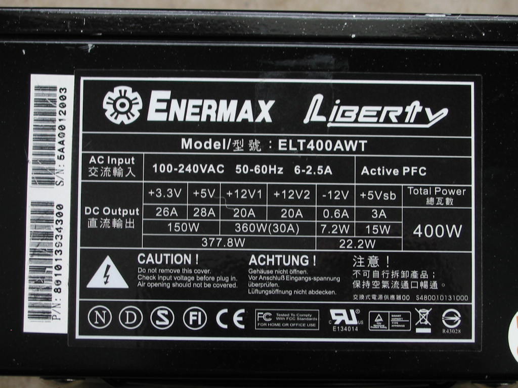
^ It's model ELT400AWT. Given the strong 3.3V and 5V rail ratings, this is also a fairly out-of-date product… but still viable for a low-mid power modern PC.
Now the label looks nice and pretty above. But the rest of the PSU did not when I got it. To give you an idea, here are some “before” pictures of what the PSU looked like when I got it (minus the few dust balls I removed - don't like to store dusty hardware):
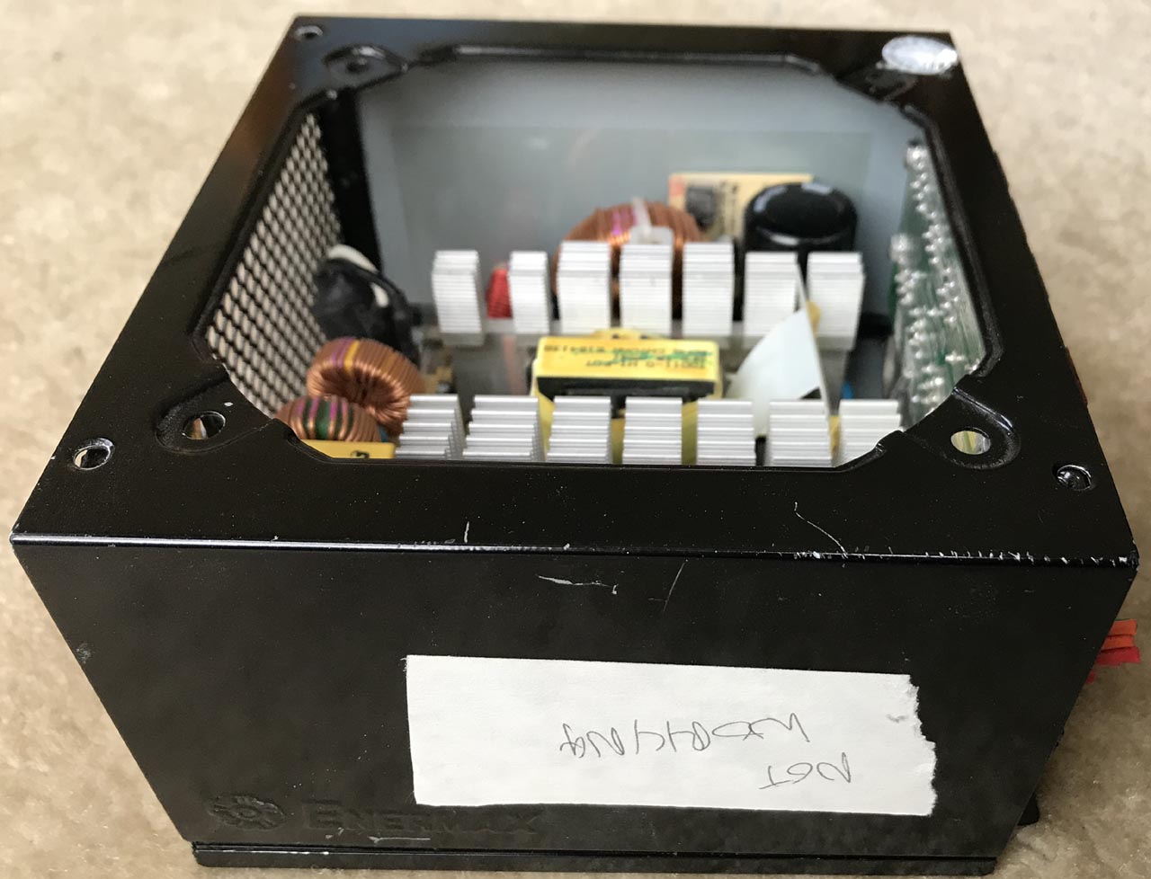

As you can see, the fan's missing, output wires are cut, and someone put a “Not Working” label on the case. Clearly it was destined for the scrap heap… which would have been a shame, as Enermax PSUs are designed fairly well. The bad caps aside, I'm pretty sure this PSU can do the power ratings on its label.
And speaking of which, let's see the rest of the PSU built quality (though I will skip doing a thorough breakdown here like I normally do.)
https://www.badcaps.net/forum/attach...1&d=1613372320
https://www.badcaps.net/forum/attach...1&d=1613372320
https://www.badcaps.net/forum/attach...1&d=1613372320
https://www.badcaps.net/forum/attach...1&d=1613372320
^ Crap caps aside (and cut wires), there isn't that much to complain about here. It's an older group-regulated design with a mag-amp 3.3V rail. If I remember correctly, the 3.3V rail rectifier looked like a 40 Amp –rated part. Same goes for the 12V rail, which was coupled to the rectified DC side of the 5V rail (i.e. 12V rail is a super-imposed 7V rail on top of the rectified 5V rail for better cross-regulation.) And speaking of the 5V rail, I think that one had two 40-Amp rectifiers. So all in all, it's a 5V-heavy PSU also capable of heavy 12V loads (probably depending on transformer output turns ratios and coupled inductor windings.)
Primary side has APFC with a 400V, 330 uF Hitachi HP cap - good, but not great, given that it's only rated for 400V and 85°C. At least it really is a Japanese brand, like the PSU's product page states. APFC controller is an UCC3817 located on the small daughterboard by the primary cap, along with a LM393 comparator. Meanwhile, the PWM controller is a UC3842bn (actually visible in one of the pictures above.) And the 5VSB also has its own PWM IC, mounted on the solder-side (it's a small 6-pin SMD - SOT-23-6, if I'm not mistaken), but I forgot to look up its numbers.
Speaking of the solder side, here's a high-resolution picture of that:
https://www.badcaps.net/forum/attach...1&d=1613372320
PCB is marked:
"ENERMAX
PCB0130-1
2005/09/29
Anita Chiu"
Wow! For a 2005 design, this was actually quite good! Back then, PCI-E and SLI were still a new thing, so even some of the most “decked out” SLI PCs would have been satisfied with the power offered by this PSU.
Back to PSU discussion… this is one thing I never really liked too much about Enermax PSUs – somewhat messy soldering. In particular, here's one thing that really caught my eye while working on this PSU:
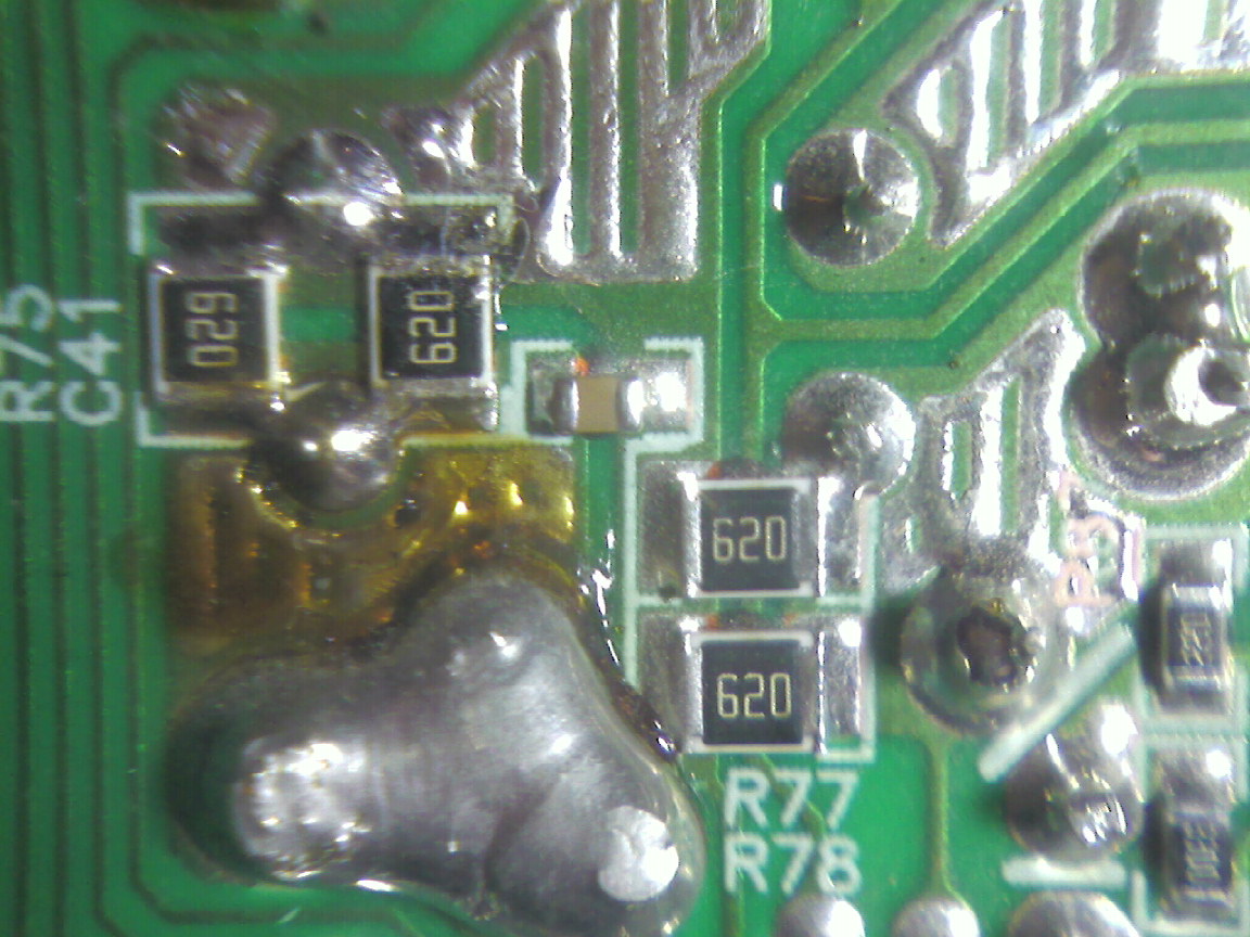
See those 62-Ohm SMD resistors? Those are the dummy-load resistors for the 3.3V rail. And that big blob of solder on the lower-left is nearly shorting the 3.3V rail to ground. It was literally just a flux crust separating the two from shorting out!
Apart from the excess solder on some joints, the PCB soldering is acceptable.
Thus, I knew I'd eventually go around to repairing it. One year later and we're here. First shown is the label below, so anyone reading can see what PSU we're dealing with here.
^ It's model ELT400AWT. Given the strong 3.3V and 5V rail ratings, this is also a fairly out-of-date product… but still viable for a low-mid power modern PC.
Now the label looks nice and pretty above. But the rest of the PSU did not when I got it. To give you an idea, here are some “before” pictures of what the PSU looked like when I got it (minus the few dust balls I removed - don't like to store dusty hardware):
As you can see, the fan's missing, output wires are cut, and someone put a “Not Working” label on the case. Clearly it was destined for the scrap heap… which would have been a shame, as Enermax PSUs are designed fairly well. The bad caps aside, I'm pretty sure this PSU can do the power ratings on its label.
And speaking of which, let's see the rest of the PSU built quality (though I will skip doing a thorough breakdown here like I normally do.)
https://www.badcaps.net/forum/attach...1&d=1613372320
https://www.badcaps.net/forum/attach...1&d=1613372320
https://www.badcaps.net/forum/attach...1&d=1613372320
https://www.badcaps.net/forum/attach...1&d=1613372320
^ Crap caps aside (and cut wires), there isn't that much to complain about here. It's an older group-regulated design with a mag-amp 3.3V rail. If I remember correctly, the 3.3V rail rectifier looked like a 40 Amp –rated part. Same goes for the 12V rail, which was coupled to the rectified DC side of the 5V rail (i.e. 12V rail is a super-imposed 7V rail on top of the rectified 5V rail for better cross-regulation.) And speaking of the 5V rail, I think that one had two 40-Amp rectifiers. So all in all, it's a 5V-heavy PSU also capable of heavy 12V loads (probably depending on transformer output turns ratios and coupled inductor windings.)
Primary side has APFC with a 400V, 330 uF Hitachi HP cap - good, but not great, given that it's only rated for 400V and 85°C. At least it really is a Japanese brand, like the PSU's product page states. APFC controller is an UCC3817 located on the small daughterboard by the primary cap, along with a LM393 comparator. Meanwhile, the PWM controller is a UC3842bn (actually visible in one of the pictures above.) And the 5VSB also has its own PWM IC, mounted on the solder-side (it's a small 6-pin SMD - SOT-23-6, if I'm not mistaken), but I forgot to look up its numbers.
Speaking of the solder side, here's a high-resolution picture of that:
https://www.badcaps.net/forum/attach...1&d=1613372320
PCB is marked:
"ENERMAX
PCB0130-1
2005/09/29
Anita Chiu"
Wow! For a 2005 design, this was actually quite good!
Back to PSU discussion… this is one thing I never really liked too much about Enermax PSUs – somewhat messy soldering. In particular, here's one thing that really caught my eye while working on this PSU:
See those 62-Ohm SMD resistors? Those are the dummy-load resistors for the 3.3V rail. And that big blob of solder on the lower-left is nearly shorting the 3.3V rail to ground. It was literally just a flux crust separating the two from shorting out!
Apart from the excess solder on some joints, the PCB soldering is acceptable.
Attached Files
if you find these attachements useful please consider making a small donation to the site

 ) and pull out the wire(s) with perfect tinning. No excess solder blobs or partially-tinned wire. Perfect results every time!
  And lastly, for the PSU top cover - it too was missing its original screws. So what I did is I took the counter-sunk M3-threaded screws from the modular board and used those on the top cover. Meanwhile, since the modular board doesn’t really care about nicely counter-sunk screws, I just used 4 spare M3 screws from my junk box to hold it in place. After all of that hacking and piecing together with random scrap parts I had acquired over the years, this was the result:
 Yeah, I was intending to do that at last *before* installing the PSU in its case... and I forgot.
 ") The other one is an old-ass Hyper Type-R PSU... because it reminded me too much of FNF, Honda Civics, and V-tech just kicked in, yo!
The other one is an old-ass Hyper Type-R PSU... because it reminded me too much of FNF, Honda Civics, and V-tech just kicked in, yo! 

 thats too much, i guess.
 since u like doing things hands on and the hard way.
  hehehe!


 ) After all of this and giving the NTC thermistor a slight push towards the primary heatsink / APFC MOSFET, I was able to fit everything in there and install the primary cap again.
 so dont quote me on that...


Comment