Announcement

Collapse
No announcement yet.

CCFL inverter boosting?

Collapse
X
 
  • Filter
  • Time
  • Show
Clear All
new posts

    CCFL inverter boosting?

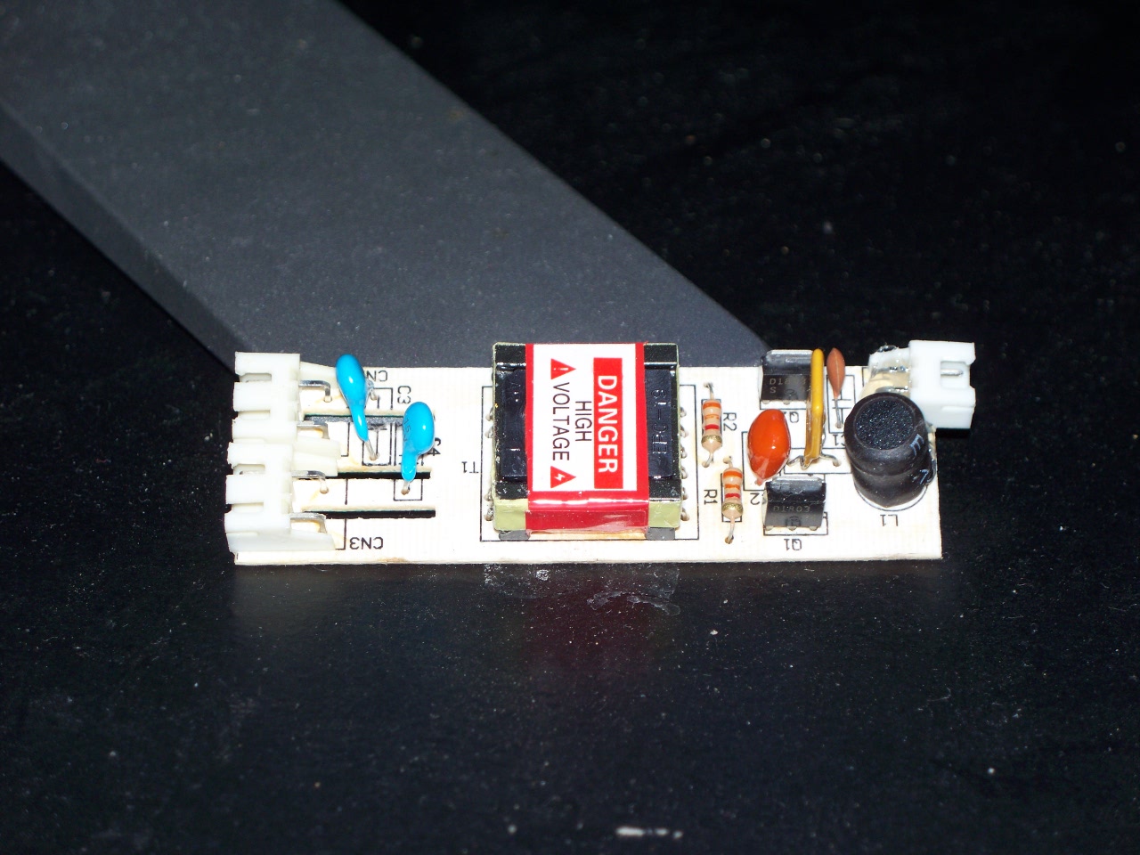
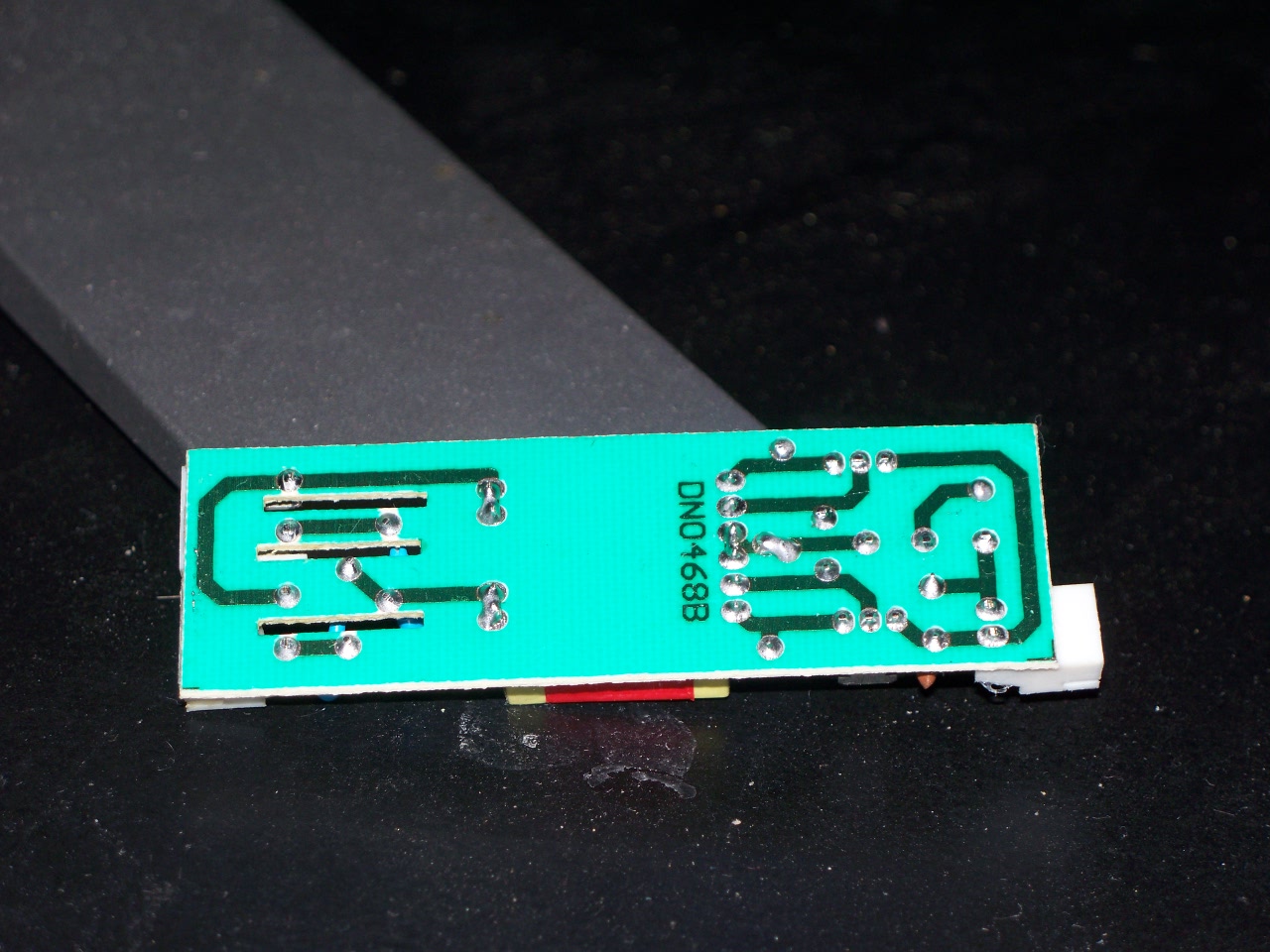
    Due to a few ordering mishaps I've wound up with a couple of Logisys 15" UV CCFLs, with no inverter, and an inverter that is supposed to power 2 12" CCFLs. Here are some pictures of the board in the inverter.


    Anyway, it isn't providing quite enough power to light up both 15" CCFLs at a decent level. Once lights up all the way, but not very bright, the other lights up about 1/2 of the tube.

    Is there a way I can modify the circuit so that it provides enough power? I understand this might not be a good idea long term, but I only need to run it for about 10 minutes. After that I'll put it back the way it was. However I need to get this done by Friday or Saturday, and I don't have enough time to order the right inverter.

    Thanks in advance.
    Attached Files

    #2
    Re: CCFL inverter boosting?

    No comments? Not even a "You're a crazy idiot!" ?

    Comment


      #3
      Re: CCFL inverter boosting?

      Originally posted by torin3
      No comments? Not even a "You're a crazy idiot!" ?

      Try using a higher supply voltage. Have a fire extinguisher or bucket of sand handy.

      PlainBill
      For a number of reasons, both health and personal, I will no longer be active on this board. Any PMs asking for assistance will be ignored.

      Never be afraid to try something new. Remember, amateurs built the ark. Professionals built the Titanic.

      Comment


        #4
        Re: CCFL inverter boosting?

        you're not using the tubes that go with that inverter i assume? if you are using the ones that came with it, seems to me it should power both evenly. the circuits look pretty parallel on each side, if you switch the tubes around, does you get the same result on the other tube, or is it the same tube that lights up halfway?

        maybe try taking off the 3.3k resistors and go 3k flat? i dunno, too technical for me really

        Comment


          #5
          Re: CCFL inverter boosting?

          PlainBill, it takes 12V. Should I pick up a 15V wall wart from radio crap and test it with that?

          ssl6, the same tube has the problem when switch from socket to socket.

          Also, I thought the resistors were 3.1K? Orange/brown/red/gold

          Comment


            #6
            Re: CCFL inverter boosting?

            Originally posted by torin3
            PlainBill, it takes 12V. Should I pick up a 15V wall wart from radio crap and test it with that?

            ssl6, the same tube has the problem when switch from socket to socket.

            Also, I thought the resistors were 3.1K? Orange/brown/red/gold
            I had a similar situation with the cheap inverters I picked up with some CCFLs ($5.00 for a half dozen of each IIRC). Using a variable power supply, I had to run the supply voltage up to 16-17 volts (no indication what the design voltage was) to get monitor CCFLs to fire at full brightness. A 15 volt wall wart may do it (make sure it will supply 3/4 amp).

            PlainBill
            For a number of reasons, both health and personal, I will no longer be active on this board. Any PMs asking for assistance will be ignored.

            Never be afraid to try something new. Remember, amateurs built the ark. Professionals built the Titanic.

            Comment


              #7
              Re: CCFL inverter boosting?

              That inverter is a fire hazard waiting to happen there is no protection circuitry on AT ALL.

              It looks like you've got an LC circuit driving the 2 driver transistors with 2 HV filter caps (in blue) on the secondary.

              Good inverters usually have a PWM IC driving the 2 transistors the PWM IC has integral protection built in. Which will kill the HV in the event of a failure on the secondary.

              If a CCFL ever dies or shorts while being powered by that thing get ready for fireworks.

              It's just like a gutless wonder power supply enough components for it to run but not enough components for it to run safely.
              Last edited by Krankshaft; 11-27-2009, 06:01 AM.
              Elements of the past and the future combining to make something not quite as good as either.

              Comment


                #8
                Re: CCFL inverter boosting?

                yeah, trash the inverter, its trouble waiting to happen.
                sigpic

                (Insert witty quote here)

                Comment


                  #9
                  Re: CCFL inverter boosting?

                  Ok, it sounds like if I want to keep the CCFLs, I should buy or build a better inverter.

                  Any suggestions on where to find plans? Or a good quality (possibly slight adjustable) inverter?

                  Thanks!

                  Comment


                    #10
                    Re: CCFL inverter boosting?

                    oh, they are 3.1k....i thought the colors were orange/orange/red, my bad

                    but seems like you've got better advice to follow now. if you do find diagrams for making an inverter, post back, i might actually be interested

                    Comment


                      #11
                      Re: CCFL inverter boosting?

                      Hi,
                      I have been on this forum for a month and I am grateful to receive very welcomed assistance. I have not been providing much myself however.

                      So here goes nothing:

                      I have found a useful resource in CCFT inverters that can be recovered from flat bed scanners. Some are 12Vdc and some are 24Vdc.

                      The 3 pin power connector on the inverter boards that I have recovered have the power inputs labeled. The middle pin is generally the on/off signal (no guarantee). After the battery and ground are connected then take the middle lead to battery or ground and the CCFT should illuminate.

                      I use these inverters to test the CCFTs in flat screens to eliminate them as defects. I made up an adapter for connecting the CCFT under test to the flat bed scanner inverter.

                      I use DC wall pack supplies to power these inverters. The voltages out of these supply outputs can be over by 50% and do not seem to affect the inverter performance. i.e. rated for 12Vdc @ 200ma and is putting out 18Vdc @ 100ma.

                      Anyone reading this post should know that the voltage generated by the inverter is not to be taken lightly (no pun intended). And the CCF tubes have mercury vapor inside (as far a I know) and should only be handled and stored with care and proper ventilation of course.

                      For what it is worth.

                      rgs,
                      Kevin
                      Attached Files
                      Be yourself,
                      everyone else is taken.

                      Comment


                        #12
                        Re: CCFL inverter boosting?

                        I would be interested in building a safe CCFT supply as well.

                        This responds to interest in finding or perhaps developing a DIY circuit for a safe and cost-effective CCFT inverter.

                        Perhaps this is best handled as a new post though...?

                        Well; the attached resources may further this discussion.

                        The basic.bmp circuit and framebarnew.pdf were found at: http://pkrobot.freehostia.com/LCDRepair.htm

                        What do you think?

                        rgs,
                        Kevin
                        Attached Files
                        Be yourself,
                        everyone else is taken.

                        Comment

                        Working...
                        X