Re: Gateway FPD1976w / LE1936 Inverter Madness
Since your monitor might be a different revision than this thread, you should start a new thread and include pictures of the top and bottom of the power board and the top of the vga/dvi board. Check the sticky on how to take pictures and post them. Someone will help you. In the mean time start making a list of your caps with UF and Volts along with height in mm. You will probably need to replace them.
Also do you have a multimeter and soldering iron? Do you know how to use them?
-
Re: Gateway FPD1976w / LE1936 Inverter Madness
Hello,
I am new to these forums and new to LCD monitor repair. I am experiencing the same issue where my Gateway LE1936 will turn on for one second, off one second, on one second, and then finally off. I have replaced all the capacitors on the power board to no avail. As a last-ditch effort, I purchased a brand-new replacement power supply board from Singapore; and it is still exhibiting the same symptoms. Do you think it could be something related to the backlight CCFL lamps? Are these replaceable? If so, how do you disassemble the the LCD screen itself with this particular model? Any help would be GREATLY appreciated.
Kind Regards,
-Mark B.Leave a comment:
-
-
Re: Gateway FPD1976w / LE1936 Inverter Madness
In my own stupidity -by not taking the time to label with CCFL leads I reversed them after flipping the power board over on the bench. Now with the 4 connectors seated properly, I am getting correct waveforms on all 4 inverter primaries and no more hot transformer or lamps. Still would not stay on.
Traced the problem to a noisy line on the v-sense to the pwm. Tracing the circuit shows an RC filter on that line. In an effort to calm down the line, I added an extra RC filter, similar to the smd components already in place. (I did not remove the orig.) The extra RC removed about 1/2 of the ripple on that line, but not the average DC volts which read a steady 1V before and after.
She is now working - I will not say fixed until after a week or so of 8 hour days. Exciting really..the first computer panel I have worked on.
I did fix a samsung 46 inch lcd TV before. That thing toasted it's pwm controller and burnt up it's power FET. First time smd soldering on that too. Replaced PWM and FET and still working 3 months now.
I have a dim Dell in the trunk. It's next.Leave a comment:
-
Re: Gateway FPD1976w / LE1936 Inverter Madness
My experience of working with a scope has been automotive, and yes there were more things to look at besides secondary ignition.
In using a scope I have found it very important to know what type of pattern I was looking at, and what a good pattern looks like.
You are lucky to have a scope available to you.
My suggestion would be to look at the good side of the inverter and see what a normal pattern looks like, and then look at the bad side.
You can easily swap a component side to side of the inverter and see which component causes the pattern to change sides.Leave a comment:
-
Re: Gateway FPD1976w / LE1936 Inverter Madness
Good job on the pictures and troubleshooting so far, but in the future, please attach your pictures using the manage attachment function here and please do not post inline for the following reasons listed at
https://www.badcaps.net/forum/showpo...5&postcount=12
Thank you.Last edited by retiredcaps; 06-03-2011, 06:43 PM.Leave a comment:
-
Re: Gateway FPD1976w / LE1936 Inverter Madness
I swapped both sets of leads and the transformer still was hot. All joints were soldered on caps, transformer and everything else that didn't look right. Solder generally looked good all over.
Here come the pictures...
It sure looks to me like the drive on the hot transformer has way too much spikes. What could cause this?
I'll wait for some comments before I translate the location of the transformers first. Then translate the location of the mosfets to see if I can isolate any component.
My workzone:

backside of power/inverter board:

and

frontside of power/inverter board:
drive signal to cool transformer:

drive signal to hot transformer:
drive signal to mosfets from pwm on cool transformer:
drive signal to mosfets from pwm on hot transformer:

12v DC rail: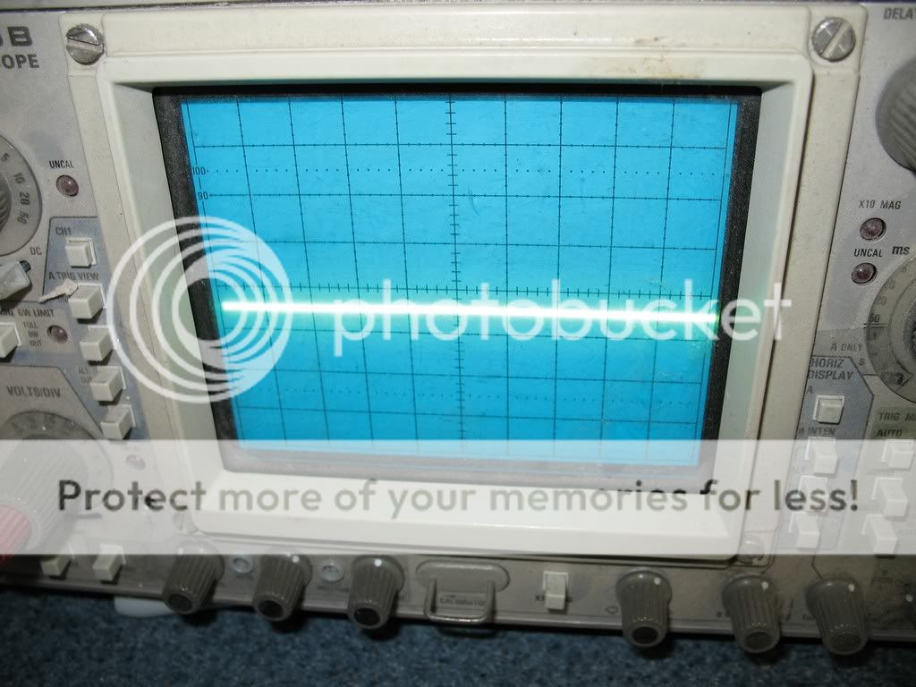
capacitive couple on output of hot transformer to lamp:
capacitive couple on output of cool transformer to lamp:
Leave a comment:
-
Re: Gateway FPD1976w / LE1936 Inverter Madness
I would have bet real money on a transformer with shorted turns.
When you swapped lamp leads, you swapped both bottoms for both tops?
And the same transformer got warm?
Dumb question, did you check solder joints on the transformers and related components?Leave a comment:
-
Re: Gateway FPD1976w / LE1936 Inverter Madness
^
I'll leave this to the engineering Guys/Gals.
I have started to run into transistor problems where something is being held on to long, and causing what I think is causing the circuit to draw excessive amperage.Leave a comment:
-
Re: Gateway FPD1976w / LE1936 Inverter Madness
I swapped the position of the lamp leads and the problem remains exactly the same. Guess the bulbs are ok.
Ohm'ed the transformer primary and secondaries. 2.8 ohms on both legs to common on both transformer primaries. 618 ohms on both secondaries. Cannot detect any problem on transformer with resistance measurements.
Pictures coming soon.Last edited by boomer9999; 06-03-2011, 06:13 AM.Leave a comment:
-
-
Re: Gateway FPD1976w / LE1936 Inverter Madness
Switch the positions of the CCFLs[move top ones to the bottom, and bottom to top]see if the problem follows the bulbs.Leave a comment:
-
Re: Gateway FPD1976w / LE1936 Inverter Madness
The hot transformer indicates a problem (Duh!!! - Like you didn't know that already!)
1. Measure the secondary resistances of the two transformers. If they don't match, the one with the lower resistance is shorted.
2. Swap the CCFL leads that normally go to the 'hot' transformer to the 'cool' transformer and vice versa. If the same transformer does not get hot it's a problem with CCFLs or leads. If the same 'hot' transformer still gets hot, it's not the CCFLs or leads.
3. Swap the transformers. If the 'Hot' transformer gets hot in the new position, it is bad. If it doesn't, you have eliminated the transformer.
4. Swap the driver ICs. Again, does the problem follow the IC, or not.
Someone had a similar problem about a year ago. I don't recall if we ever were able to resolve the problem.
Of everything I've lost as I got old, I miss my mind the most.
We prefer working with pictures of YOUR board. That way we can spot potential causes.
PlainBillLeave a comment:
-
-
Gateway FPD1976w / LE1936 Inverter Madness
Hi,
I'm new here. Working on my first LCD repair!!
OK, it is opened up on the bench. Power on the display, the lamps in the panel power up for about 1 sec. then turn off, then turn on for about 1 sec. then remain off. The blue led power button remains on. (display from PC is working correctly and is visible with flashlight when inverter is down)
All caps look fine on the outside. Scoped the DC and everything is smooth.
I tacked a 1 meg resistor from vsense on pwm to ground to keep the inverter running. 1 of the 2 inverter transformers gets very hot and the waveforms on the mosfet drive have huge 100 volt spikes on the leading edge of both half of the primary side of inverter. The other transformer has clean signals. Bringing the scope near the HV traces shows the hot transformer is got the same output as the cool one - a nice sinewave.
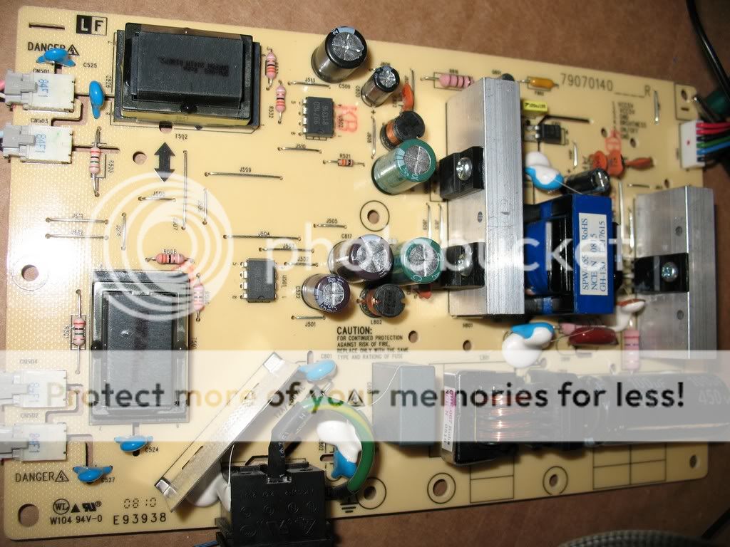
This is the board I'm dealing with:
https://www.badcaps.net/forum/attach...1&d=1303052623
I have tried replacing one cap at a time with the spares I have and there is no change.
Help


-
 I just got this tv today and it appeared to have no backlight on. After taking off the rear cover and checking again in the dark I can see that MAYBE one quadrant is lit.. But still it's quite dim. I was going to check the LEDs with my tester, and I found LED 1 and LED 2 + pins on the wire from the inverter, but I couldn't identify a ground. Nonetheless I tried using a mounting screw on the inverter board and also the chassis as ground but regardless my tester reads 300 which is what it reads when there is no voltage draw.
I don't know how exactly to test the inverter itself. Is it... -
 I have a tripp-lite aspint 3636vr inverter charger which blow some of mosfet transistors. I replaced them repaired also the driver circuit and tested but the mosfets burn again.
It work very well as inverter and also as charger if I let the rear switch in auto mode (inverter) and charger only(charging) but in auto when I connect the feed line 220V AC first time it pass ok to line and start charging the batteries but when I remove the feed line it pass to inverter mode and if I do it again the second time when passing from charging to inverter the Main transformer start making a...03-06-2023, 07:07 AM -
 For some reason I'm just not going to let this 19" TV defeat me. I guess because I have a schematic to work from I feel like I'm oh so close.
History- while adding a turn-on circuit I let a small screw roll under the power board. Worked through all of that circuitry, probably replacing a MOSFET and PWM controller that were not bad but I was following the service manual. Finally figured out that the power supply is in working order when the inverter section (for the backlights) is disconnected. When the +12 supply to the inverter is disconnected the +12 and +5 will come up... -
If I had a solar fed grid tie inverter (GTI), a modified sine wave inverter, and a power outage occurred, what would happen if you disconnected mains, backfed the modified sinewave inverter (MSI) into house power, and hooked up the GTI to the output of the MSI, would it work?
Next thing is trying to charge the batteries using solar power, but that's another issue ... -
 I am currently on a troubleshoot of 46” Sony KDL-46BX450 tv. I came back from Washington to Texas on medical emergency and had to leave all my tools up there. All I have is a couple of screwdrivers and a dvm. I wish to ask the community a troubleshooting question. Please forgive stupid questions as meds I am taking produce brain fog.
I have well maintained Sony KDL-46BX450. It went black one day. After turn-on, I get solid green light and Sony logo in screen center for about 1-2 seconds, then black. No blinking LEDs, no hissing. Flashlight test shows screen characters dimly viewable,...
Leave a comment: