Re: Subwoofer Power Supply Problem
It may be a bda connection that makes the pops, or like what 999999999 said,
it could be AC spikes. My computer subwoofer pops and crackles when you turn the fan on in the other room.
-Ben
-
Re: Subwoofer Power Supply Problem
^ Pops seem more likely to be AC line spikes.Leave a comment:
-
Re: Subwoofer Power Supply Problem
I replaced the same two caps Bob mentioned, C78 & C66 , I used some Nichicon 1000uf 35 V radial caps I had on hand. The bad ones were Rec brand and one of them was swollen. I'll get the other values & complete the repair soon because I'm getting some odd pops at random times through the sub. I have a heatsink that I may mount to the plate, maybe that will help.Last edited by sfox; 11-21-2011, 07:22 PM.Leave a comment:
-
Re: Subwoofer Power Supply Problem
I'm a little confused Bob in St Louis, your C78 and C66 don't look blown, did you pull them off and do an ESR test to find them faulty?
As for the large red wire, trace the circuit as it might just be an alternate location. I wonder if they moved it at some point because they found the adjacent capacitors were prone to fail so they didn't want the wire with its cement fortification impeding removal of a faulty capacitor.
The review you linked makes some very curious claims like Tracking Down Converter topology supposedly sensing input signal and lowering voltage, and yet I see no subcircuit on this PSU that would provide that functionality... and having read that it makes the review statement that an "Intelligent Parameter Control System... monitors woofer voice coil condition and sends data to the amp to correct and prevent..." seem all that much more dubious.
Don't get me wrong, it looks like a nice sub well worth repair and the hiss may be bad caps even though they don't look vented in the picture. I think I'd go ahead and replace C16, C17, C18, and C19 while the board and soldering iron were out... they're going to be inexpensive and possibly a bit degraded by the heat which was the likely cause of the C66 and C78 problem... ideally picking a 105C rated part.Leave a comment:
-
Re: Subwoofer Power Supply Problem
By the way, any of you thinking the repair isn't worth it, should check >> THIS PAGE << for a review of the product, including it's original MSRP of $599.
Bob
Leave a comment:
-
Re: Subwoofer Power Supply Problem
Hey all.
A fellow gave me two of these Onix UFW-10 subwoofers because of the hum.
Lucky me.
Didn't take long to find this very helpful forum, and thread. Thanks to all for posting. I'll be ordering the talked about replacement caps very soon.
The one item I thought was interesting, was that even though it's the same model number subwoofer (UFW-10), and the same model number power supply (ULW-10), and the same (apparent visual) circuit topology, I find it very interesting our "bells and whistles" are much different.
Plus, the large red wire shown in a previous post is in a different location than mine is.
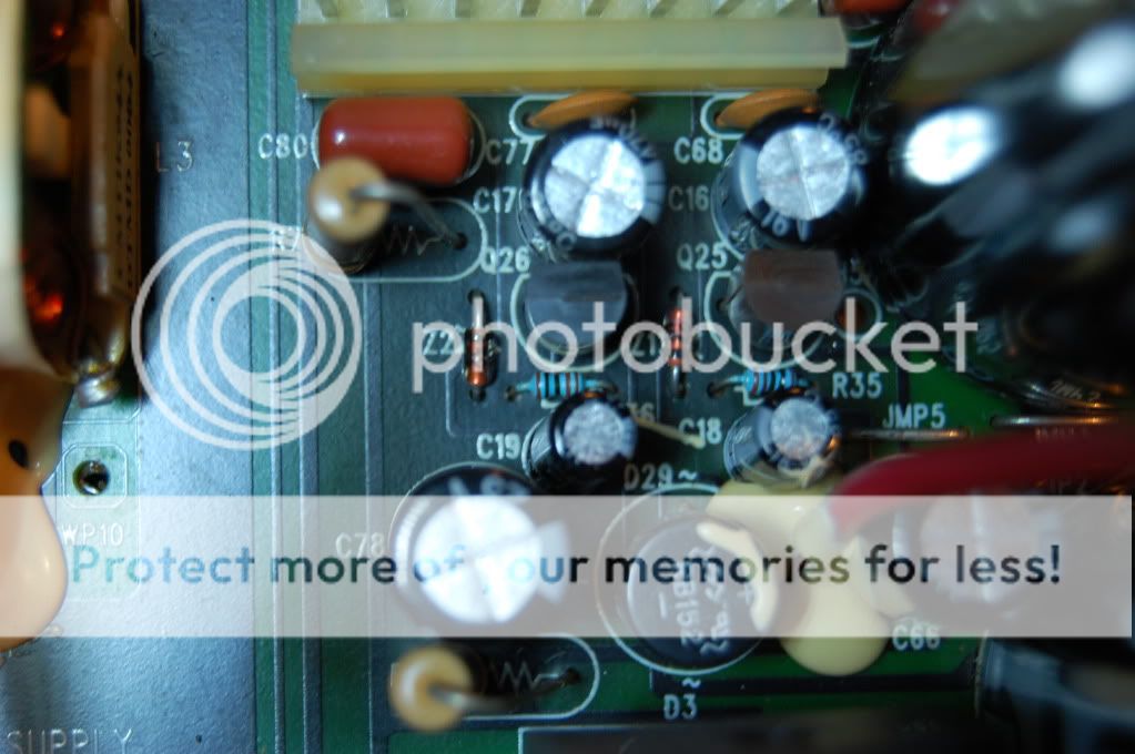
Here's a few photo's of the back (outside) of my amp, the (inside) of the amp, the power supply (with model # showing) and a close-up of the power supply itself.
Note; the location of large red wire.
I think I'll only be replacing the two blown caps (C78 and C66)
I'll order two of each cap, obviously, one set for each subwoofer.
I'll keep in touch and let you know what happens.
Bob
p.s. "sfox", contact me. What are you going to do?


Leave a comment:
-
Re: Subwoofer Power Supply Problem
My bad, thanks for the help, many nines!Leave a comment:
-
Re: Subwoofer Power Supply Problem
sfox, being a different amp and possibly different problem you should probably post a new forum topic.
If it has a passive crossover, yes you could just substitute a different amp. If active, you'd need that portion of the circuit and the supply for that portion of the circuit to still work, then take the (input to the amp stage) output from that to your external amp.
Personally, I think I'd try to fix the amp in it instead... you didn't mention what is wrong but if it can be fixed with reasonable effort it seems a waste not to do so, unless it wasn't performing to your requirements and you feel the separate amp will do so.Leave a comment:
-
Re: Subwoofer Power Supply Problem
I'm a new member with a busted UFW-10. Mine makes no sound at all. Has anyone tried modding one to use an outboard amp with the existing crossover & such? I have an old pro amp that would work well. Thanks!Leave a comment:
-
Re: Subwoofer Power Supply Problem
I did the dirty deed too, swapped out all 6 caps and fired it back up. The hum was gone!
Unfortunately, it's still not working, but I don't know if it's because something else is broken or I'm not feeding it the right signal. It's not going from standby to "on", which it should do if it sees a signal on the LFE input. It also won't kick off into "calibrate mode" or generally make any sound at all. But that's a topic for another thread.Leave a comment:
-
Re: Subwoofer Power Supply Problem
Just fixed mine! Thanks a lot for the information guys!Leave a comment:
-
Re: Subwoofer Power Supply Problem
Avanilla, I'm sorry the caps were Panasonic caps not Mullard. The big black round cylinders are the caps. They are radial caps, that means they have two lead protruding out the bottom. Look on the side of the cap there will be a color bar which forms an arrow near the bottom. That indicates the lead next to it is the negative lead. make sure when you replace the new cap with the same orientation as the old one (note where the old cap arrow/bar is located). Unsolder the old cap use solder wick or a solder sucker. heat up the solder joint and either wick the solder off or used the solder sucker as you heat the joint. Resolder a new cap into place (note the proper orientation) make sure the solder flows like a liquid around the joint before you stop heating it.
Digi Key P/N: 565-2946 ND
Good luck!Leave a comment:
-
-
Re: Subwoofer Power Supply Problem
Do you happen to have the part number?Leave a comment:
-
-
Re: Subwoofer Power Supply Problem
My Rocket ULW-10 has been sidelined for over a year because of a dreadful hum/buzz. Now, thanks to this forum, at least I understand the problem. What I don't have is the knowledge and experience for working on circuit boards. Can you give me a "step by step" procedure? At the moment, the only step I don't need help on is the removal of the screws that hold the plate to the back of the enclosure. Thanks!Leave a comment:
-
Re: Subwoofer Power Supply Problem
From what I see on the picture it is that there are two separate PSU circuits on the board, being fed by different transformer windings for different voltage.
You have a large SIP style diode bridge feeding the two big 2200uF/160V caps a high(er) DC voltage, these are filtering the power rails for the output stage of the amp.
You also have a smaller bridge rectifier right behind the first one, it's the little black round button that has "+ - and HY and RB1" visible. Then you have a couple of filter caps C18/C19, then it looks like a basic zener shunt regulation circuit which charges up C16/C17.
I wrote two separate circuits instead of three because I suspect the two low voltage regulated circuits are actually just positive and negative rails for an opamp or opamp-like circuit on the amp board.
There are lots of ways to improve this power board. The best one is probably to get rid of it and make your own. By making your own you could use linear regulators for the two low voltage rails, use higher capacitance for the high voltage rails, BUT you start running into more and more work since this uses connectors and probably just fits in a certain spot in the cabinet.
Leave a comment:
-
Re: Subwoofer Power Supply Problem
Oh I see, you just pulled some random caps no one has talked about of a photo posted a year and 1/3 ago...
No wonder I didn't know what you were talking about.
The 1000uF have nothing to do with the 2200uF.
The 2200uF seem to be on the AC side.
As to 1000uF being enough filtering that depends on the value of the inductor, how many caps there are in parallel, and how many other filters are in the thing.
In something audio it makes more sense to locate additional filters close to the amp circuits on the other boards after all the connections and wire runs than to try to do all the filtering on the power board.
.Leave a comment:
-
Re: Subwoofer Power Supply Problem
Look at the pictures. There are two 2200uF 160V caps. The caps that failed were 1000uF.
I didn't think caps with such low capacitance could filter a linear power supply for a 350W amp.Leave a comment:


-
I did not have any 27uf @ 50 volt capacitors but one nice thing is that it has enough room for two capacitors in parallel a 22uf and a 4.7uf @ 50 volts 22 plus 4.7 equals 26.7uf which so very close to 27uf I will show some pictures of it sometime tomorrow
This is one of the shit est boards I seen in a very long time and it was the daughter board the traces just lifting off the board I had to use the capacitor leads to repair the the traces and the main board is not any better because I had to repair several traces for the daughter board to the main board
After all of... -
I have been working on this concept for quite some time now with limited success but recently I found a switching power supply that is setup for the voltage that this soldering station needs to operate at however it also needs part of the secondary circuit from the original switching power because you need several voltage rails
I once tried to get a ZD-915 desoldering station to work on a 18 volt battery power supply but unfortunately things did not go well but I did find a work around but I might try this idea again but going at a little differently more about this another time... -
 Vizio e601i-A3 - Has Sound and Display, But No Backlight - Bad Power Supply Board or Bad LED Bulbs ?I was given this TV from my great uncle. He said it just wouldn't turn on one day out of nowhere, replaced the TV, and gave it to me to possibly fix and use for myself.
Upon bringing it home and plugging it up, it showed a standby light.
I powered it on and without a flashlight, the display showed the "V" but the lighting is very dim, but visible.
The screen seems to blackout and stay black, but with a flashlight I can see the display.
With my Playstation 4 connected via HDMI, and running a game I can hear sound.
Assuming... -
 Hi all, I just need to know that, can i use SMPS type power supply to test and short circuit detection on a laptop motherboard?
I saw 95% of repair guys are using only Linear bench power supply. linear bench power supply is pricy, thats why i planned to get one SMPS supply.
i know that in linear power supply the noise will be very low comparing to SMPS supply.... -
 Good day.
I have an AC/DC -> DC PWM (rectifier + 555 buck converter) power supply with MDF11n60, which is getting very hot.
The input is AC from a transformer and the output powers a 24v dc fan. The power supply is used to regulate the speed of the fan.
After several runs on the bench power supply I noticed that the mosfet is reaching 80+C*. The mosfet reads fine on component tester, the thermal paste is changed, the fan is cleaned and with freshly oiled bearings.
When powered directly from the bench psu, the fan takes ~0.7A on 12V. The current consumption is similar...
Leave a comment: