Announcement

Collapse
No announcement yet.

Eurocase 350W PSU

Collapse
X
 
  • Filter
  • Time
  • Show
Clear All
new posts

    #21
    Re: Eurocase 350W PSU

    Btw, interesting topic brought by trodas. I can't resist not to polute the thread I wonder if it should be moved to PSu section.. I search this thread yesterday and can only found it by tracking my own post

    Trodas, That 2000uF is probably a bit low for the pi filter (configuration of cap - coil - cap) and true that most of the cheap PSU of 300W-360W i have opened only have 2000uF total in paralel for each rail. But they work. Come to think about it again, their only true wattage probably are only 150-250W range. Now if you want to know what the (relatively) high quality PSU of 300W, i have a 300W old Fortron (FSP300-60BT) with 4700uF single cap each on 5v and 3.3v. The coils on the pi filter are larger AWG, impossible to find on those cheap PSU.

    So, it appears that even the true 300W PSU has 4700uF on their rails except for the 12v (1000uF + 1650uF). It's old atx spec though, low requirement on 12V. On every cheap PSU I recap because of badcaps or just for the badcaps prevention, i replace those 1000uF with at least 1500uF Sanyo WG (preferably Nichi HE 3300uf 16v 12.5mm), or keep using 1000uF but this time using good old Rubycon ZL (10mm 1000uF 16v $0.15). They migh not be non-aquaous caps but they are at least 4000h 105C caps i feel safe to use.

    So i think what ideal for the 300W (cheap) PSU recaping is:

    3.3v -> 2 x 2200uF (100% upgrading)
    5v -> 2 x 2200uF (100% upgrading)
    12v -> 2 x 1500uF (50% upgrading)


    BTW in more advanced/higher wattage PSU like on my Tt 480W, i found:

    3.3v -> 2 x 3300uF
    5v -> 2 x 3300uF
    12v -> 1000uF + 2200uF

    Note that they are all ATX v1.3


    On Silverstone 360W ATX v2.01 :

    3.3v -> 2 x 3300uF
    5v -> 2 x 2200uF
    12v -> 1000uF + 2200uF


    With the stock caps i have, for the modern PSu (V2.x ATX), i can recap them as follow:

    3.3v -> 2 x (3300uF 6.3v 10mm) (0% upgrading)
    5v -> 2 x (3300uF 6.3v 10mm) (50% upgrading)
    12v -> 2 x (3300uF 16v 12.5mm) (100% upgrading)

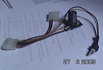
    Or if i can't squeeze the space, i use 1500uF 16v 10mm caps for 12v rails as it is the bigest capacitance i can get in 16v 10mm caps. They are Sanyo WG, so their ripple current rate are just perfect. To compensate lower capacitance, i use higher uF/lower ESR caps on mobo and vga cards (jap brands). For hd or optical drive that need 12v rail, i don't sure if LESR or low ripple is more important factor than the capacitance for such constant load in the line, but IMO anything larger than 2x1000uF on secondary side caps PSU (12v rail) is safe. Anything but taiwan/chinese crap caps. But if you use more than six hardisk then you may think you need a capacitor bank for the 12v rail (or simply add a second PSU). Do you ever read about power lead made by OCZ? Many will wonder about its (effective) functionality but i think i's a very smart idea (caps, ceramic caps, and iron core on the end of mollex connector).

    I made it a year ago (a laughable design, only caps, led, and small pcb). I lost interest before i attemp to make a better circuit.


    Trodas, i can only found 2200uF 16v 10mm in Panasonic FK. If the PSU is for my equipment only probably i can tolerate using those hi spec Samxon. But that hi spec and small dimension samxon caps just scared me if it for using in PSU, too much water in it maybe? (It's the question remains to be answered). The teapo SC 2200uF 16v 10mm usually found on the PSu is even low spec (1.7 mA permissible ripple currrent). If space is not a problem, using 12.5mm ZL, YX*, FC, HE, LX*, is preferable. (Dont say they are garbage just because ther are worse spec than MCZ or GA ).

    For the input filters caps, so far I never found Jamicon or Hitachi. But if they are Teapo LXK i would keep them. IME they are proof to life long at least 3 years. But if they are another cheap taiwanese/chinese brand with the same rating but suspiciously smaller dimension compared to their japanase counterpart, i feel the urge to remove them, although i dont think bigger dimension will justify it will last long or immune to heat. What i think is that it's the electrolyte formula and perfect manufacturing that play the bigest role in here. What gonzo said about this is very informative (that large caps made by cheap brand should have fairly good quality)


    Panasonic TS-ED 680uF 200V r22x45 Load life is 3000h but 105°C and ripple - see page SIX on TWO paged document - so, ripple is unknown and that is all the decision problem I have now...
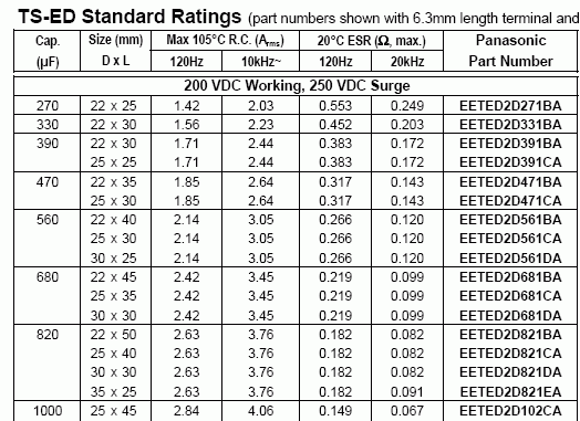
    Weird, at that spec (105C 120Hz TS-ED) i see it has 2420mA allowable ripple and 0.219 ohm ESR (20C 105C). Page six where? Maybe on this?


    And do you rate this as overkill even if you include the fanless operation?
    I mean - bigger cap dissipate heat better - because it is bigger
    But they are larger can and so they are blocking the airflow greater. But i agree they are much higher heat resistance (comparison within the same series and elct formula/technology).

    trodas, i think it will be better to replace the heatsink directly with that copper than just mounting that copper on the heatsink. Or you may replace with a better performance (custom made) heatsink. Once you try it, you may realize it's not a delicate job. What i done is also isolating the chip/diode totaly from the heatsink with good insulator such shinetsu thermal paste/glue (remove also the thermalpad). I could be wrong but from my experience it's not necessary to make the heatsink as a ground path for the chip/diodes. i cant explain but i never found any problem with it.

    The PC case usually allow wider PSU case, so you may make a totally new PSU case from thick copper that connected to primary and secondary heatsink so it will make a very big passive heatsink. Be carreful as you may send AC voltage to the system. (continuity tester is our saviour).


    And I never measured it, so how can I know if they lost some capacity?
    Dont you have an LCR meter or at least DMM with capacitance measuring ability?

    Still think that in case of knowingly bad caps is waiting a good idea?
    The best time to recap is when the hardwares still new. It will be better than new. But Im not suggesting you to void the warranty. If you have dual (two same hardware), recap one and see what the different after several years. That's what i lately do, i'll have something to write about it in the future.

    Sometime bad caps do not instantly make a bad hardware, it depends on the quality of the hardware design. I wait 4-5 month until i recap my epox board with 9 doomed gsc caps (see my GSC pics on the hall of shame thread), the board was still functioning fine (read: folding) before then. IIRC a little bit instability here and there but it never shutdown suddenly when it was folding..


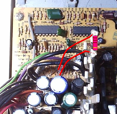
    Now the filtering. After my bad experience with the PSU I wanted to make sure that nothing bad will happen again. So, what should I do? Block (bridge) each of the big output caps with 10uF 16V ceramics?
    Will that help enought? Or should I also add in parallel 100nF 16V ceramics to this?
    Isn't that job already taken by the input filter (or by AC filter, EMI filter, or such)?

    I even make a soft startup circuit between the plug wall and the PSu in my boring time. That's only to make me understand how the input filter works.


    ----
    Some question im just too afraid to ask:

    Will a fairly large amount of capacitance in secondary side of a PSU sustains/tortures the scottchkies? If yes, to what degrees (if not, why)? Will it need a change in coils requirement (both big and small coils in the secondary)?

    Are those dummy resistor (low ohm high wattage) also responsible for discharging those secondary caps immediately after the system shut off? BTW they are so hot i need to mounted it on the hs, otherwise it will burn the pcb.

    Attached Files
    days are so short when you actually do something..

    Comment


      #22
      Re: Eurocase 350W PSU

      In my experience, Panasonic FK is an outstanding series - low ESR, good endurance, moderately high ripple current, and most important - small can sizes. I've only used the 1500/6.3/8 mm - and they work very well for general-purpose bypass and VRM applications. That 2200/16/10 mm would be a near-perfect universal replacement capacitor with better specs than the Taicon HD 1200/16/10 mm that I'm using now. AFAIK, FK is a discontinued series, replaced by FJ, FM, etc.

      Comment


        #23
        Re: Eurocase 350W PSU

        yanz - WTF mate was that? LOL
        First, I envy you. I can't get any decent cap there and the only way I can obtain some is trough friends (or the the inferior problems and payments with customs and caps directly, together with very expensive (26$ flat or 120$ FexEx) postage...) from Digi-key (Pannyes, some Nichicons but not low ESR nichicons, just these ones like HE - sadly not HZ...) and or from Big Pope.
        So pls don't post for what you can get such nice Rubbyes, it make me sick of envy. Thanks

        I do agree with you, that 2000uF (2x 1000uF) is insanely low for the 3.3 and 5V rails, so that is why when today I got my package, I put there 2x 3300uF 6.3V Samxons GD d10. For the 12V rail I used a Samxon 2200uF 16V - also d10
        Also these there 470uF caps are Samxons now, a GC ones there.
        Remaining five 47uF 50V caps positions will be filled with Pannyes (hopefully soon I can get them from these customs stupids that holding them for almost a week now w/o reason just for one stupidity with addy... (must be Person to Person...) ) as well, as I going against your advice to recap the input caps as well, with Pannyes TS-ED, because these Hec caps are inferior utter crap and they smell bad. So I think it is time to off they go, straight to caps hell...

        So, my upgrade was:
        3.3V - 330% (2x 1000 to 2x 3300)
        5V - 330% (2x 1000 to 2x 3300)
        12V - 220% (1000 to 2200)

        Futhermore I blocked each of these bigger caps with 10uF 16V Murata 1210 Ceramic cap, witch bring the total ceramics used for the PSU recap to nice number 10 now (remember, I already replaced five 1uF and 4.7uF electrolyte caps by these SMD ceramics soldered from back of the PCB, of course)

        That should make my PSU run great, fanless for five, better six years - I hope. We could even took that as the fanless test of Samxons GD, hehe

        Futhermore I think that the PSUs aren't that critical on the low ESR caps, so I could get away well using these GD ones - for sure they are at least 10x better that the Hec ones, so...

        You also raised some interesting questions even I would love to see anwered, tough. Mine resistor in my Antec almost burned itself, so I would love to knoe what it is for. Also I would love to know, if these ceramics does help - I think they does, but... Because the voltage regulation is not that good and not every board have in all input voltages EMI filters - I know ony about few boards that well filter the imput and why stress it, when I could easily add caps there?
        And the question about capacity increase and stress on the regulators are also interesting, I think. I would tip that it does relieve these regulators, because the more capacity they have, the less fluctuations these mosfets have to compensate during load... But that is just a tip.

        I will ignore your recommendations about the heatsink changes, as these output heatsink are hardly warm, so I did not see the temperature as problem there. Bad caps was a problem, tough.
        Cooper cases and stuff belong to some sort of joking thread, I believe

        Anyway, thanks for explaining me the pdf - I did not realize that they rated ripple in Ampers (usualy mA are used there) and the shortcut was unknown to me too, so I wanted the page 6, as mentioned on page 1 of the pdf and this page simply does not exist. However I feel the Panny is better - even it have slightly lower ripple, it have better lifetime - 3000h at 105 instead of 85°C for Nichicon I got with panny...
        "It is dangerous to be right in matters on which the established authorities are wrong." - Voltaire
        "I believe that all the people who stand to profit by a war and who help provoke it should be shot on the first day it starts..." - Hemingway my config - my caps

        Comment


          #24
          Re: Eurocase 350W PSU

          Hey Yanz, i love this kind of thread polution .
          So i contribute alitte polution too .

          This kind of Hardware protector or however you name it, is somthing i have thought by myself too. The reason behind this where some burned HDD circuits, from wich i never knowed if the psu was the cause or the weak hdd motor driver chips used in some Maxtor and probably some Seagate models. And for GPU`s i thought on cleaning the power an stabilizing it. You probably know the advice from most GFX manufacturer to put the card on an separate wire, wich is not conected to an other device. But my unit i had in mind is a little more complex.
          Loock at the picture provided. This would be the version for HDD protection (obviousely only on not kritcal SOHO systems ). For GPU may be the fuse is a little bit problematic, due to the high currents. This unit will first save the device if overvoltage would be there by blowing the fuse with the large current the transil would sink, and finaly being the PSU to shut down due the first transil, wich is simply an short for the overvoltage wich should triger the OCP of the psu, it hopefully had build in (if not this will obviousely leed to an destroyed transil diode or a fire hazard if psu would fail before). I never build that thign, as i am using only branded psu sinc those experiences (namely Fortron, Enermax, Seasonic, Amacrox).

          Now some answers of the raised questions:

          Those small ceramic caps are filtering the noise with an higher frequency, if there is somethign e.g from the shotky rectifier (the fast on off switching will generate high frquency noise). And then they will add some low esr filtering, the large AL caps are to slow for (or more correct having a to high inductance). This will assure a very clean o/p, wich is not dealt with the I/P EMI filter, wich is to prevent the mains from some noise generated by the ccaps , the rectifier and or the APFC circuit.

          The shotky rectifier on the o/p should not be stressed mutch more, if the capacitance will be greater. Normaly, the SMPS controler should take care, that there is some kind of soft start. Then the shotkys are IMHo rated sligthly above the current handling of the transfomer, and the current wich flows during the on time of the switching transistor though the tranformer. This is at least in an simple buck step down regulater mutch greater than the o/p current. So the caps can only surge what they get through the coil /transformer and the shotky rectifier.
          This will apply at least for an well enginered psu, obviousely not for deer branded or similar ones. For those devices it is not very uncomon that the rectifier blows if concected to an seriouse load.
          This is at least, what i think. May be ( for shure in this forum) there are some more educated people about that.
          on the i/p caps, this is somhow an other situation, as there is at least for non aPFC units no regulation as only those inrushcurrent limiting NTC`s. But if you change the capacity substantially, those would may be getting overloaded.

          The reason, why i am not comfortable about adding substantially more capacitance to an circuit is the possibility to alter the bandwith of the regulation loop of those psu`S. This can either lead to an bad regualtaion and or tho an kind of oscilation of the whole circuit, wich can lead to totally unxepected behavior. Bot cases are probably not that obviousely, iunless the whole unit was cheked with an oscope during a load test. This would asshure the proper operation within a few minutes. As i do not have an oscope, i can`t do that. And i don`t want to have this feeling tho be not shure about the proper operation of your psu, similiar if you leave some caps i in wich you are not thrust.

          Regarding those high wattage resistors, i think those are either there as an shunt resistor to messure the current flowing through and therefore to generat the input signal for the controler, or as an load resistor, assuring the proper operation of the regulation circuit even if the minimal load was not provided. An other reason for those could be an current limmiter, e.g to provide the operation voltage for the controler circuit from the high voltage primary side.
          Any way. You could easily figure it out by following the traces and or by removing those resistor from an psu an see what will hapen.
          Attached Files
          Last edited by gonzo0815; 07-27-2006, 04:41 PM.

          Comment


            #25
            Re: Eurocase 350W PSU

            Hey polluters of my thread
            Now it is time to show some pics, tough my work has yet to be completed (damn cursed customs holding me back again, I knew that this is going to happen, but I can't do anything about it...). So, now my PSU output foldering caps are Samxons there:


            4x Samxons GD 3300uF 6.3V. More that enought I think, but it should not stress the regulation more, but IMHO less. Give the mosfets more room to breath with the increased capacity


            This is the D10 16V 2200uF Samxon GD cap - nice suxxka, is not it? (BTW, the gold color is exactly the same, as on Pannyes FM... coincidence? )


            470uF 16V Samxons GC.


            Supporting 10uF 16V ceramics caps That should do the trick


            And yep, you are right, gonzo0815 - after they killed my mobo, I did not trust the Hec caps at all. So - off they go from my PSU!


            "It is dangerous to be right in matters on which the established authorities are wrong." - Voltaire
            "I believe that all the people who stand to profit by a war and who help provoke it should be shot on the first day it starts..." - Hemingway my config - my caps

            Comment


              #26
              Re: Eurocase 350W PSU

              What is the purpose of the ceramic cap bridging again? Never mind. I should read better.
              BTW, I love the pics of your sister Trodas. When she turns 18, will she marry me?
              Last edited by Spacedye69; 07-28-2006, 07:36 AM.

              Comment


                #27
                Re: Eurocase 350W PSU

                The purpose of ceramics bridging cap's is to filter out fast hi-frequency spikes the electrolyte can't filter out, becuase they are so fast for it and it's reaction time won't permit efectively dealing with such spikes.

                Clearly they improve the quality of output voltage very much.


                And about my sis - I think she will want a guy, who can speak Czech well - so unless you start learning, you are out of luck
                "It is dangerous to be right in matters on which the established authorities are wrong." - Voltaire
                "I believe that all the people who stand to profit by a war and who help provoke it should be shot on the first day it starts..." - Hemingway my config - my caps

                Comment


                  #28
                  Re: Eurocase 350W PSU

                  gonzo0815, that's a great idea. but, is using the fuse just adding too much complexity? what kind of fuse we may want to use for the 5v-12v?

                  i would just stick with the pi filter design, but adding more capacitance:


                  pics is courtesy of oprekpc.com (DimZ):


                  to tell the truth, i already make that special card , but i still don't know what kind of choke/coil i safe to use... too little time for me to think and tinkering about it


                  trodas, alright, what value you will recommend for the ceramic caps? is it only 10uf 16v? i may try it as well. damn i save all my money for wedding when i really need a good digital camera...
                  Attached Files
                  Last edited by yanz; 08-18-2006, 07:07 PM.
                  days are so short when you actually do something..

                  Comment


                    #29
                    Re: Eurocase 350W PSU

                    The fuse is only for protection, e.g. it blows if to mutch current flows because the voltage is to going to high and the OV device will short the overvoltage.
                    This was only intended as an DATA safeguard for HDD, not for GFX.

                    Comment


                      #30
                      Re: Eurocase 350W PSU

                      Looks like voltage filtering fanatics take over my thread

                      Okay, singe I got my caps, I made (week ago) the finish of recap of my Eurocase PSU happen. So, in the end, I used all Samxon caps for the end filtering, replaced all the small caps with 10uF SMD ceramics and used five 47uF 50V Panny FC caps as well, as two Panny TS-ED 820uF 200V imput filtering caps:


                      Pretty, aren't they?


                      However the results I got aren't pretty, except 5V rail, tough.

                      On very mild load, 1A from 12, 5 and 3.3V rails it show this:

                      3.3V rail


                      5V rail


                      12V rail


                      And on the top of that, when I added to the mild load two harddrives on the PSU (200G WD and 80G Seagate), the ripple increased notably, hiting 70mV in the worst case on 12V rail. Also the great 5V rail get bad to 26mV, same goes for 3.3V rail, witch doubled it's ripple to 50mV.

                      That is weird. I blocked every the Samxon caps and still getting such crap? It won't help that the new Chieftec PSU got 250mV ripple - it is full of Teapos, so, no wonder... (and Chieftec indeed suxx)

                      Better PSUs could hold these ripple in reasonable limits, for sure anything over 50mV aren't good, so... I did a little experiement - I removed these 10uF SMD ceramic blocking caps on the end caps.
                      And after removing of the ceramics, the ripple got notably better!

                      Eurocase 350W ripple with ceramics:
                      12V - 70mV
                      5V - 26mV
                      3.3V - 50mV

                      Eurocase 350W ripple w/o ceramics:
                      12V - 54.4mV (11.99V)
                      5V - 18.5mV (5.11V)
                      3.3V - 53mV (3.338V)


                      Conclusion.
                      Adding ceramics into PSUs is counter-productive. Indeed they could filter the voltage a bit better, however they does trick the feedback into knowing it delivering still good voltage (the ceramics could hold and even deliver the charge for it, but not for the whole powered PC) and therefore dramaticaly increase the number of switching need as well, as increasing then ripple on load dramaticaly.
                      Don't do it.
                      It is probably still okay to add these ceramics somewhere around the PSU connector on the PC mainboard, as from such distance they could not do harm to the voltage regulation, yet I'm not now entierly sure about that anymore.

                      Anyone care to explain me what I find out?

                      PS. sadly I did not measured the ripple when there are the original Hec caps - but I fix this on the two other mine Eurocase 350W PSU's waiting for recap
                      Last edited by trodas; 08-24-2006, 04:58 PM.
                      "It is dangerous to be right in matters on which the established authorities are wrong." - Voltaire
                      "I believe that all the people who stand to profit by a war and who help provoke it should be shot on the first day it starts..." - Hemingway my config - my caps

                      Comment


                        #31
                        Re: Eurocase 350W PSU

                        ah, that's pretty but too bad the result isn't going like what you expected. i would try with a more serious load coz at light load it's very often that the measuring of PSu rails far from the optimal, but that just me. perhaps some big ceramics resistor with low ohm would be good for dummy loads.
                        days are so short when you actually do something..

                        Comment


                          #32
                          Re: Eurocase 350W PSU

                          I agree to that, load it seriousely and rechek. But adding ceramics of that size isn`t that easy and harmless, that is for shure. I think something between 0,1 - 1uf should be ok to filter high freq noise. Any other thing could easily generate severe ringing on the o/p voltage. If there i an L filter, may be it is ok to only put those ceramics at the second stage caps (e.g. the o/p caps after the inductor). Any way, near an cpu, i think it should be ok, as most desings are made for them. But again, not to mutch ceramic capacitance, as this would probably irritate the controler.

                          Comment


                            #33
                            Re: Eurocase 350W PSU

                            yanz - well, Enermax PSUs do tad better, as you checked in my other thread ( https://www.badcaps.net/forum/showthread.php?t=2389 ), so, I was expecting to get more closer, when I bump the capacitance that much. But it looks like the poor voltage regulation design can't be improved radicaly by good caps - only a bit better - and clearly it don't going to kill my cap's again, however it is also not get to the Enermax outpud voltage quality level.

                            Futhermore dummy loads are just dummy loads. They have constant load, while the load in action does differ all the time...


                            gonzo0815 - I was aware of possible consequences, and put these at the very and after the coil, however it still make things only worser. So I put them away and get better voltage.
                            Maybe at the mobo PSU connector they should be?
                            "It is dangerous to be right in matters on which the established authorities are wrong." - Voltaire
                            "I believe that all the people who stand to profit by a war and who help provoke it should be shot on the first day it starts..." - Hemingway my config - my caps

                            Comment


                              #34
                              I don't understand...

                              Todays I recaped my second of my there Eurocase 350W PSUs. This one is not modified in any way (in fact it was for the first time I ever opened it) and I did what I did to the fanless one - mixed Panny / Samxons recap. End caps Samxons, rest Panny and these 4x 1uF and 1x 4.7uF caps replaced with 10uF SMD ceramics 16V ones. All as with the previous modded fanless PSU - oh, okay, I run out of the Samxon GC 470uF caps, so I used for the there the Panny FM ones - no big deal, I think. These Pannyes are just taller that Samxons, that it is. The better specs of GC Samxons over FM Pannyes aren't important, I believe.

                              Anyway, as I promised, I took the measurments on my dummy load (1A from each 3.3, 5 and 12V rails) + two HDDs first, and then after recapping.

                              PSU was entierly same as the first one, no bulging of the Hec caps visible. There was a lot of dust and stuff, tough. First time opened from 2003 - go figure

                              Voltages and ripple measurments

                              Before recapping on dummy load
                              12.09V - 16.3mV
                              5.14V - 16.8mV
                              3.34V - 6.9mV

                              Now this if ficking amazing! This is great output voltage! I won't expecting that from anything less say Enermax 620W Liberty! How this is possible from such crappy PSU at all?!

                              After recapping on dummy load
                              12.08 - 47.3mV
                              5.14 - 24.1mV
                              3.339 - 24.1mV

                              WTF?!?! I worked so hard and all I get if WORSER results?! Now that make me angry! I don't want my work turned out to worser results that was before! WTF?! Who can explain me this, I don't know what to think...

                              After recapping on Abit ST6-R with Prime stress test running
                              12.08 - 49.6mV - 4.0kHz
                              5.14 - 13.6mV - 8.9kHz
                              3.339 - 8.7mV - 1.8kHz

                              Whoa! That is MUCH better! The 5V line is great, amazing! Now why?! The measurments was taken from the HDD connector (12 a 5V rails) so any caps on board can't play much role - not to mention that this old board did not have 12V support line and take all from 5V line, yet still don't have any input filtering caps (!), so... why any how? I did not understand what is going on, unless...

                              ...unless the fact, that we overshoot these filtering caps at the end (4x 1000uF to 3300uF and 1x 1000uF to 2200uF) means that simply the PSU need some serious load to produce clean woltage now?

                              Anyone who know better or can tip a reason why ripple after recapping on my dummy load does suxx and when runing real computer with this config:

                              ABit ST6R (raid)
                              1680Mhz Tualatin (120x14) 1.625Vcore
                              512MB SDRAM 2-2-2-5 120Mhz
                              160G Maxtor 8MB cache (6Y160P0)
                              PCI GF4 MX440 64MB 80/166
                              DVDRW NEC DV-2510A (8x DVDRW)
                              IDE 100MB zip
                              Edimax 9130TXA 100MB NIC

                              ...it show very good voltage. 13mV ripple on used for Vcore 5V rail is great and the 8.7mV on mainbard is simply outstanding Almost 50mV ripple on 12V line aren't very good, tough it is just 12V line and used mainly for the other devices that mainboard, so, acceptable.
                              "It is dangerous to be right in matters on which the established authorities are wrong." - Voltaire
                              "I believe that all the people who stand to profit by a war and who help provoke it should be shot on the first day it starts..." - Hemingway my config - my caps

                              Comment


                                #35
                                Re: Eurocase 350W PSU

                                What were the original caps - Jamicon or HEC?

                                Comment


                                  #36
                                  Re: Eurocase 350W PSU

                                  Hec
                                  "It is dangerous to be right in matters on which the established authorities are wrong." - Voltaire
                                  "I believe that all the people who stand to profit by a war and who help provoke it should be shot on the first day it starts..." - Hemingway my config - my caps

                                  Comment

                                  Working...
                                  X