Remember that cheap $15 PSU that dmill89 posted a while back here?
https://www.badcaps.net/forum/showthread.php?t=72229
.
.
So I was randomly browsing on eBay (as always) and saw a listing for supposedly the same “775 Watt” PSU with starting bid at $1. Description stated “for part or repair”, with the owner/seller mentioning the PSU had blown/shorted. Surely I could spend a few $$ more and get the same PSU as dmill89 right from Amazon brand new and (probably) working… but where is the fun in that?!
So I got this one instead for $13 shipped to my door ($0.99 for the PSU and the rest was shipping. ) If dmill’s PSU was able to handle 350 Watts without croaking, it really made me wonder what was wrong with this one. I got the unit nicely packed, and it honestly looked pretty much unused with no dust anywhere:
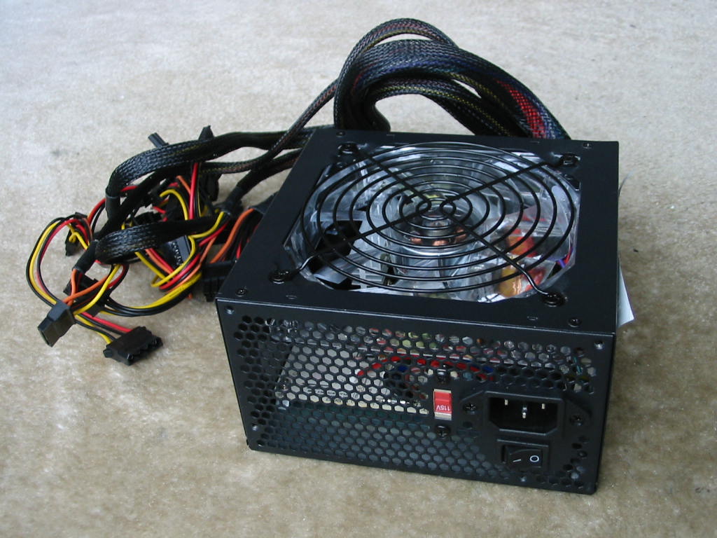
On the outside, it appears nearly the same as dmill89’s PSU: standard black finish, non-modular unit with a 120 mm fan and voltage selector switch (i.e. no AFPC.) Only difference was really that mine appeared to have a see-through fan with LEDs.
And here is a bottom-shot:
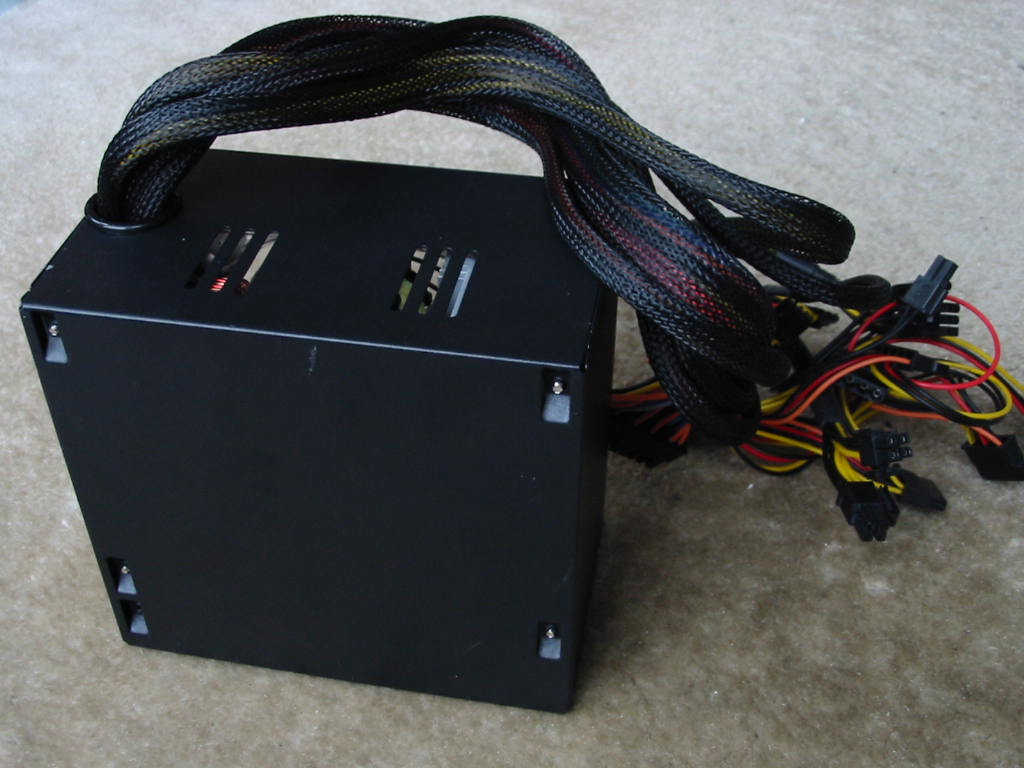
I think one way to tell if you’re dealing with a cheap PSU is when you see those stamped PCB stand-offs on the case.") On the positive side, at least there are vents on the back of the PSU to (hopefully) avoid hot spots.
On the positive side, at least there are vents on the back of the PSU to (hopefully) avoid hot spots.
Here are also all of the connectors this PSU has:
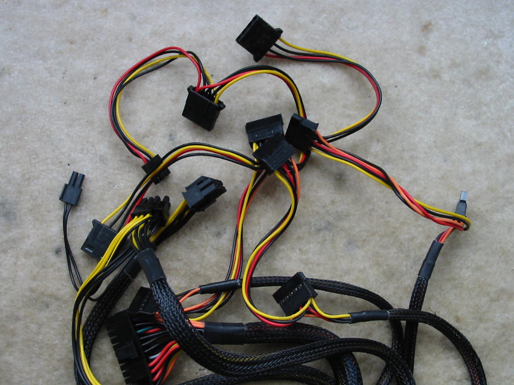
Aside from the standard motherboard stuff (20+4 pin ATX, 4+4 pin 12V CPU power), this unit also has 2x 6+2 pin PCI-E 12V power, 6x SATA, 3x Molex, and 1x floppy/Berg. The output wires are a mix of 18 and 20 AWG, with the ATX connector, 4+4 pin 12V CPU, and first 6+2 pin PCI-E connector being 18 AWG. The 2nd 6+2 pin PCI-E is simply piggy-backed from the 1st one, but with 20 AWG wire. The Molex and SATA connectors are also all 20 AWG. I do like how they arranged the drive connectors though, with 2x SATA followed by a single Molex on each string. And all wires are UL listed, at least.
OK, let’s have a look at the label finally.
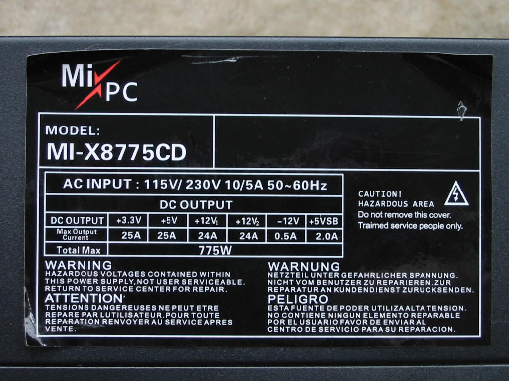
It appears like this is not the same PSU model as dmill’s. Whereas his was an MI-08775V2 and rated for 875 Watts, this one is a MI-X8775CD and *only* rated for 775 Watts… like we are going to believe that one, too. What’s funny is that label keeps peeling off by itself. While I was taking the case shots above, I had to re-apply pressure on it at least several times to stop it from rolling onto itself and falling off. It’s as if it knew it was telling me lies and so was shamefully trying to cover itself, fall off, and hide somewhere.
On a different note, I’m surprised the shipping box didn’t get blown away by the wind when the unit was delivered to my house. There’s not much weight to this PSU. Probably a good half of it is from the output cables. On the other hand, all those output cables scare me - imagine someone trying to plug in a beefy video card with two 8-pin PCI-E power connectors! Technically speaking, since there are supposedly two 12V rails rated at 24 Amps each and no mention of the total max combined current, one could assume this unit is capable of 48 Amps (or 576 Watts) on the 12V rail. But maybe that is possible on this unit, after all. What do I know if I haven’t opened the unit yet? I suppose that part comes next.
But first, would it B OK if I posted a picture of the fan? (Oh look at me trying to be funny now.
  )
)
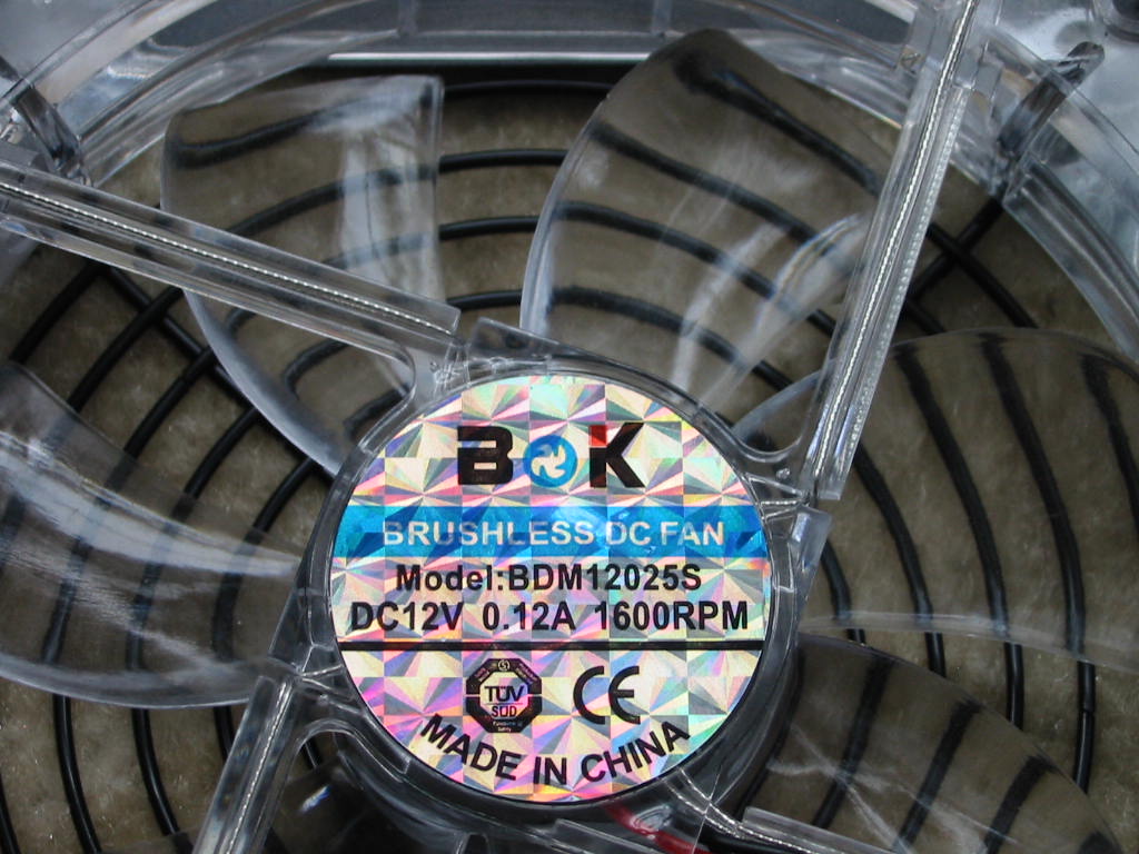
This one is a rated for 0.12 Amps - just a tad lower than the one in dmill’s PSU. When I hooked it on 12V directly, it does move quite a bit of air, though. And the blue LEDs are very bright and pretty. (Perhaps that also explains the lower rated power of the PSU - those LEDs need a lot of juice, so they had to lower the rating on the unit. )
Anyways, here is the unit inside.
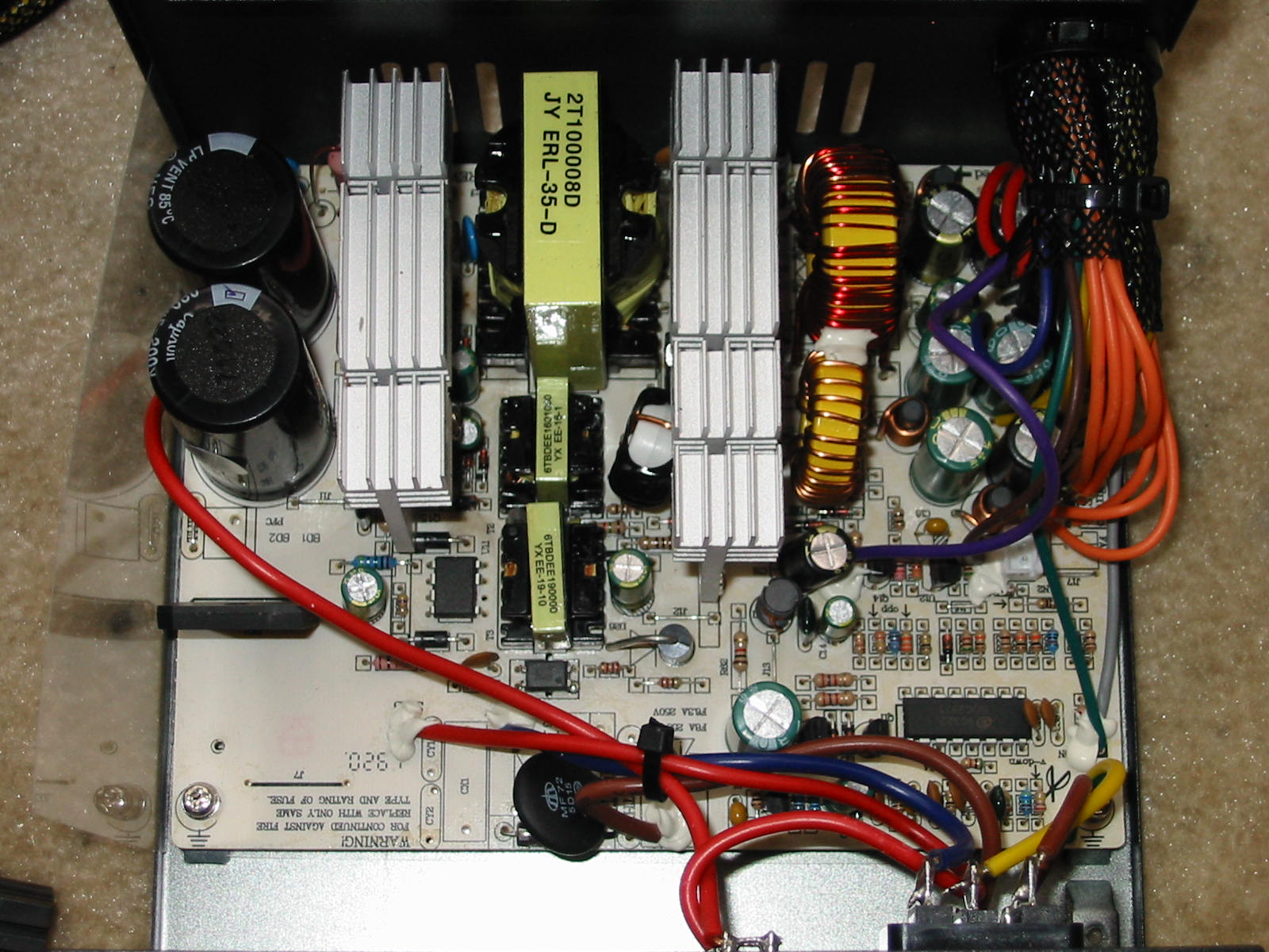
Right off the bat we can see… well, there isn’t a whole lot to see, really. Initially, I thought this might be a 300-350 Watt capable unit. Sure the input filtering is missing, but I expect that to a degree in any cheap PSU. What really got me, though… before I had the unit opened and was looking through the vents, I was honestly very excited, because I could see two TO-3P transistors on the primary heatsink and a PDIP-16 chip on the secondary. This got me thinking the PSU must use the same double-forward design as the 875W unit, but perhaps also with added OCP (due to that PDIP-16 IC.) Then after opening the unit, I looked at the parts on the primary heatsink and noted the “13009” text on what I thought was one of the MOSFETs. Surely this quickly extinguished my excitement.
- That ain’t no MOSFET! That’s a BJT.
And only then I saw the obvious - that there are 3 transformers in the middle. The realization hit me like a rock on the head… this is yet just another half-bridge PSU. Looking up info on the SDC2921 PWM controller confirms this 100%.
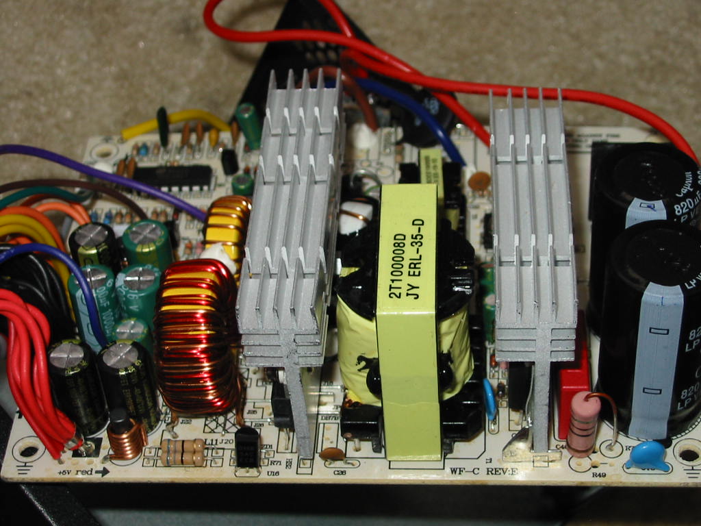
Ah well, at least the thing has a bridge rectifier and a properly-sized (tall) 35 mm main transformer. The heatsinks are also not bad. Certainly we can’t expect 775 Watts from that. Heck, does a half-bridge design over 500 Watts even exist as far as ATX PSUs go? If yes, I don’t want to know how much one of those weights or what kind of BJTs it has on the primary. It certainly won’t be anything like you see in the pictures above. But anyways, let’s continue forward.
I think I see what blew up in there.
Interestingly enough, the fuse (a free e-cookie for anyone that can find it ) was intact. I suppose this part (and perhaps others) blew up to save the fuse, as usual. 5VSB should still be good, though. It uses a 3313D IC (whatever that is, I can’t seem to located a datasheet) and has the typical 50V, 47 uF “startup” cap.
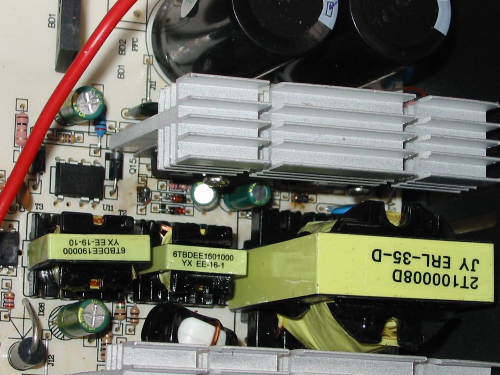
Time for an autopsy on the primary, so out goes the heatsink.
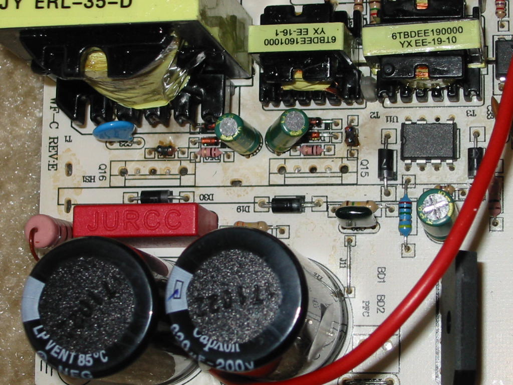
We have not one but two charred small “components”. Initially, I thought these were diodes, but the PCB silkscreen suggests they are resistors. I get quite different readings for the two, despite both being connected the same way. Next to these, you may also see two small 1-Ohm resistors (one in front of Q15, and the other to the right of Q16 Base) - these are blown open. One even appears to have a hole / burn mark on it. The reverse-polarity diodes might be OK, though. Will check if/when I decide to dig deeper into it.
Next, here’s our beloved MOSFETs…. Oops sorry, I meant BJTs.
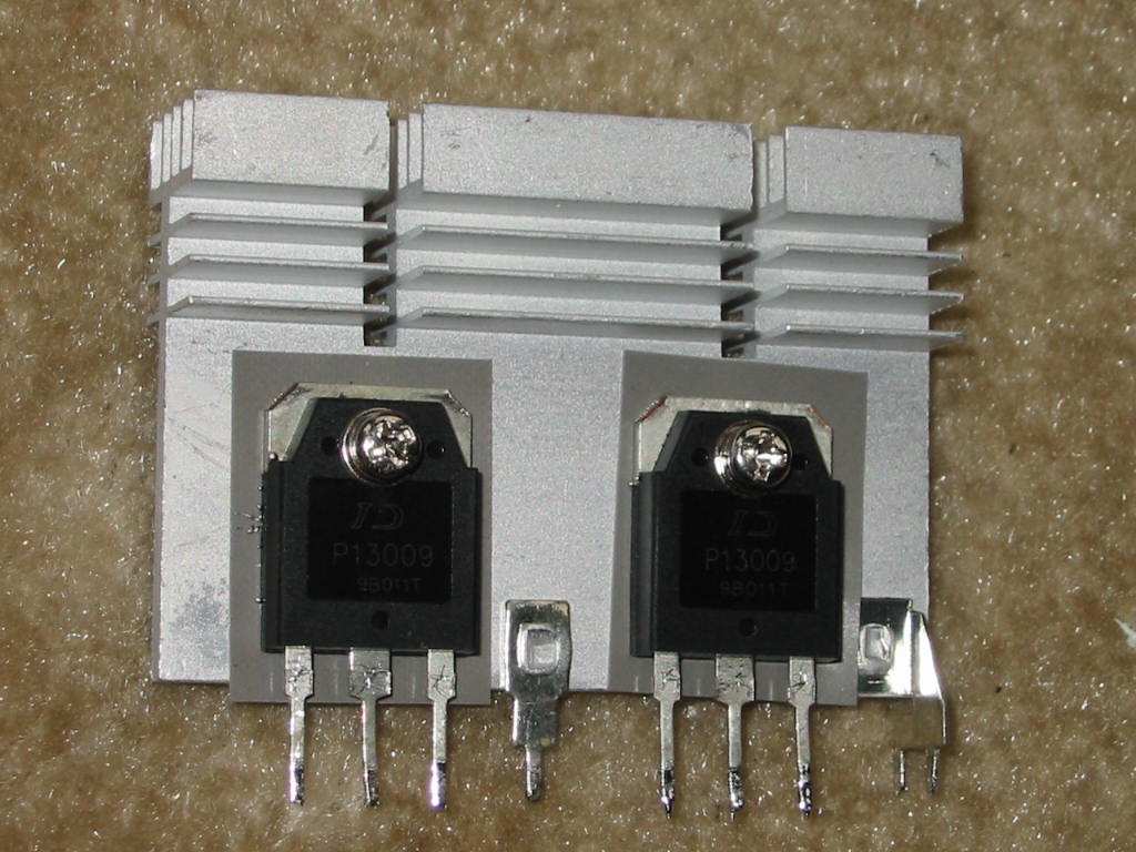
They look OK, but they are NOT OK. The left one is completely blown open on all pins. The right one has a short between Base and Collector. The Emitter has decided it won’t talk to these two in any way - completely open in any direction. Given the no-name manufacturer (or at least I can’t seem to find it), no telling if these are knock-offs or real 13009. I suspect it may be the former. In any case, the MIGHTY fuse defeated them.
Speaking of which, I think this picture just barely shows the fuse… among other parts.
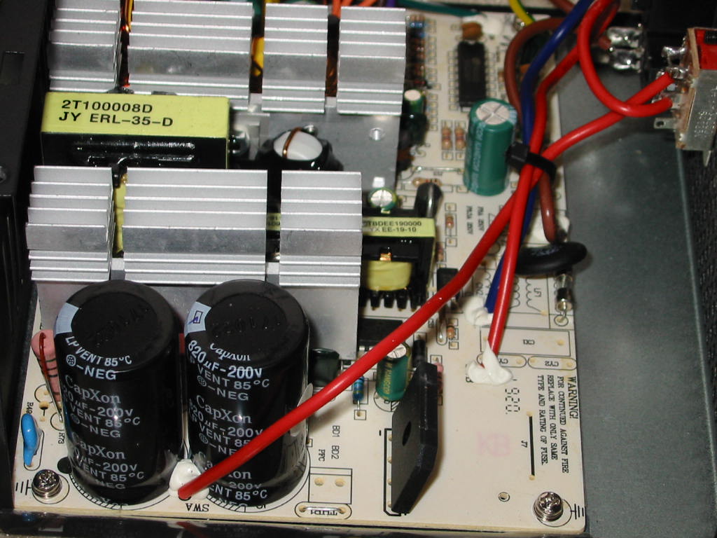
For the primary caps, we get a pair of CapXon LP, 200V, 820 uF… in 22x42 mm size. IMO, that is suspiciously small for that capacity. I shall find out later.
  Also interesting to note there is a 2nd spot for a thermistor (which is bridge by a jumper, since there is one already) as well as an empty spot for a connector for PPFC coil. As for the blue cap on the left of the CapXon’s: that should be a Y2-class cap between ground (earth) and negative (-) primary-side bus… but surely enough, it ain’t Y2-rated and rather just a standard 2.2 nF, 2 kV ceramic cap. In terms of EMI/RFI, this PSU certainly won’t pass… and hence why we don’t see any FCC or UL marks on the label.
On the other hand, the PCB doesn't seem so bad, at least on the solder side:
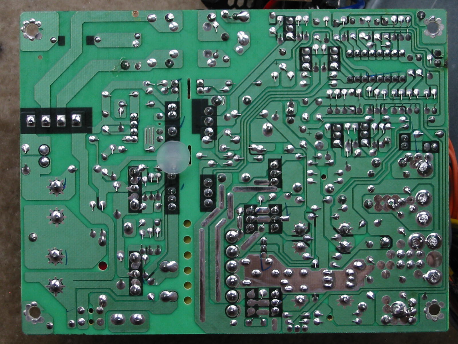
The soldering is very good, overall. Spacing between primary and secondary might be a bit questionable in a few places... but overall, nothing too serious, it seems.
continued in part 2 below due to 10k char limit...
https://www.badcaps.net/forum/showthread.php?t=72229
.
.
So I was randomly browsing on eBay (as always) and saw a listing for supposedly the same “775 Watt” PSU with starting bid at $1. Description stated “for part or repair”, with the owner/seller mentioning the PSU had blown/shorted. Surely I could spend a few $$ more and get the same PSU as dmill89 right from Amazon brand new and (probably) working… but where is the fun in that?!
So I got this one instead for $13 shipped to my door ($0.99 for the PSU and the rest was shipping.
) If dmill’s PSU was able to handle 350 Watts without croaking, it really made me wonder what was wrong with this one. I got the unit nicely packed, and it honestly looked pretty much unused with no dust anywhere:On the outside, it appears nearly the same as dmill89’s PSU: standard black finish, non-modular unit with a 120 mm fan and voltage selector switch (i.e. no AFPC.) Only difference was really that mine appeared to have a see-through fan with LEDs.
And here is a bottom-shot:
I think one way to tell if you’re dealing with a cheap PSU is when you see those stamped PCB stand-offs on the case.
On the positive side, at least there are vents on the back of the PSU to (hopefully) avoid hot spots.Here are also all of the connectors this PSU has:
Aside from the standard motherboard stuff (20+4 pin ATX, 4+4 pin 12V CPU power), this unit also has 2x 6+2 pin PCI-E 12V power, 6x SATA, 3x Molex, and 1x floppy/Berg. The output wires are a mix of 18 and 20 AWG, with the ATX connector, 4+4 pin 12V CPU, and first 6+2 pin PCI-E connector being 18 AWG. The 2nd 6+2 pin PCI-E is simply piggy-backed from the 1st one, but with 20 AWG wire. The Molex and SATA connectors are also all 20 AWG. I do like how they arranged the drive connectors though, with 2x SATA followed by a single Molex on each string. And all wires are UL listed, at least.
OK, let’s have a look at the label finally.
It appears like this is not the same PSU model as dmill’s. Whereas his was an MI-08775V2 and rated for 875 Watts, this one is a MI-X8775CD and *only* rated for 775 Watts… like we are going to believe that one, too.
What’s funny is that label keeps peeling off by itself. While I was taking the case shots above, I had to re-apply pressure on it at least several times to stop it from rolling onto itself and falling off. It’s as if it knew it was telling me lies and so was shamefully trying to cover itself, fall off, and hide somewhere. On a different note, I’m surprised the shipping box didn’t get blown away by the wind when the unit was delivered to my house. There’s not much weight to this PSU. Probably a good half of it is from the output cables. On the other hand, all those output cables scare me - imagine someone trying to plug in a beefy video card with two 8-pin PCI-E power connectors!
Technically speaking, since there are supposedly two 12V rails rated at 24 Amps each and no mention of the total max combined current, one could assume this unit is capable of 48 Amps (or 576 Watts) on the 12V rail. But maybe that is possible on this unit, after all. What do I know if I haven’t opened the unit yet? I suppose that part comes next. But first, would it B OK if I posted a picture of the fan?
(Oh look at me trying to be funny now. This one is a rated for 0.12 Amps - just a tad lower than the one in dmill’s PSU. When I hooked it on 12V directly, it does move quite a bit of air, though. And the blue LEDs are very bright and pretty. (Perhaps that also explains the lower rated power of the PSU - those LEDs need a lot of juice, so they had to lower the rating on the unit.
)Anyways, here is the unit inside.
Right off the bat we can see… well, there isn’t a whole lot to see, really.
- That ain’t no MOSFET! That’s a BJT.
And only then I saw the obvious - that there are 3 transformers in the middle. The realization hit me like a rock on the head… this is yet just another half-bridge PSU.
Looking up info on the SDC2921 PWM controller confirms this 100%.Ah well, at least the thing has a bridge rectifier and a properly-sized (tall) 35 mm main transformer. The heatsinks are also not bad. Certainly we can’t expect 775 Watts from that. Heck, does a half-bridge design over 500 Watts even exist as far as ATX PSUs go? If yes, I don’t want to know how much one of those weights or what kind of BJTs it has on the primary. It certainly won’t be anything like you see in the pictures above. But anyways, let’s continue forward.
I think I see what blew up in there.
Interestingly enough, the fuse (a free e-cookie for anyone that can find it
) was intact. I suppose this part (and perhaps others) blew up to save the fuse, as usual. 5VSB should still be good, though. It uses a 3313D IC (whatever that is, I can’t seem to located a datasheet) and has the typical 50V, 47 uF “startup” cap.Time for an autopsy on the primary, so out goes the heatsink.
We have not one but two charred small “components”. Initially, I thought these were diodes, but the PCB silkscreen suggests they are resistors. I get quite different readings for the two, despite both being connected the same way. Next to these, you may also see two small 1-Ohm resistors (one in front of Q15, and the other to the right of Q16 Base) - these are blown open. One even appears to have a hole / burn mark on it. The reverse-polarity diodes might be OK, though. Will check if/when I decide to dig deeper into it.
Next, here’s our beloved MOSFETs…. Oops sorry, I meant BJTs.
They look OK, but they are NOT OK. The left one is completely blown open on all pins. The right one has a short between Base and Collector. The Emitter has decided it won’t talk to these two in any way - completely open in any direction. Given the no-name manufacturer (or at least I can’t seem to find it), no telling if these are knock-offs or real 13009. I suspect it may be the former. In any case, the MIGHTY fuse defeated them.
Speaking of which, I think this picture just barely shows the fuse… among other parts.
For the primary caps, we get a pair of CapXon LP, 200V, 820 uF… in 22x42 mm size.
IMO, that is suspiciously small for that capacity. I shall find out later. Also interesting to note there is a 2nd spot for a thermistor (which is bridge by a jumper, since there is one already) as well as an empty spot for a connector for PPFC coil. As for the blue cap on the left of the CapXon’s: that should be a Y2-class cap between ground (earth) and negative (-) primary-side bus… but surely enough, it ain’t Y2-rated and rather just a standard 2.2 nF, 2 kV ceramic cap. In terms of EMI/RFI, this PSU certainly won’t pass… and hence why we don’t see any FCC or UL marks on the label.On the other hand, the PCB doesn't seem so bad, at least on the solder side:
The soldering is very good, overall. Spacing between primary and secondary might be a bit questionable in a few places... but overall, nothing too serious, it seems.
continued in part 2 below due to 10k char limit...
Attached Files
 I suspect this may even be on of those cases where the user just built a new system with this PSU, powered it On, and the thing blew up almost instantly or in very short order.


 from the factory. Let's not shed any tears.

 Finally!
 )
)
 For a moment, I thought I might have to do some trace cutting and other rewiring to get everything done properly. But then I figured an easier solution:


Comment