
So I was bored yesterday (and avoiding my homework) so I decided to come up with a circuit that would keep the PSU fan spinning after you power down the computer. The only way I could think of to do this off of the 12v was with a giant capacitor...and that wouldn't work so well....so I made one that runs off the +5vsb rail.
Here is the schematic:
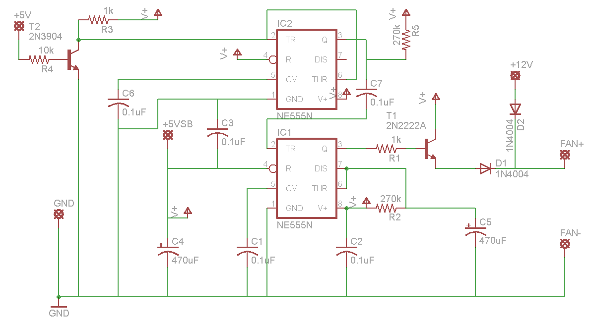
The little "V+" things that look like umbrellas are all linked to the +5vsb, I used them to avoid cluttering it up.
It uses two 555 timers, a 2N2222A transistor and a 2N3904 transistor. One change though from the schematic, for D1 and D2 I used 1N5819 schottky diodes, so there'd be less voltage loss. My EAGLE libraries don't have that part though. I tried to make many of the component values the same to minimize the number of different parts. R2 and C5 control the length of time the fan runs after you power down - with these values it runs between 2 and 2.5 minutes. I know there are probably better, more efficient ways to do this, but I used the parts I have on hand. I know that PSU fans are 12 volt, and some won't run on only 5 volts, but this runs then at 12 volts (minus the diode voltage drop) until the PSU turns off, and then the 5 volts kicks in. Withe the two fans I tested this on (one 80mm and one 120mm) the 5 was enough to keep them spinning.
It uses the +5v rail to detect whether or not the power supply is on or not. The 3904 and IC2 are there to take this slowly falling signal (because of the capacitors) and make it a short instantaneous drop, so that it triggers IC1. The +12v connection is there to power the fan when the PSU is on. The diodes protect the other parts of the circuit from voltages that aren't supposed to be there.
I used a 0.6ohm resistor to measure the current draw of the circuit. With the PSU on and the fan running off of 12v, the circuit uses about 10mA from the +5vsb. With the PSU off and the fan running off the +5vsb, it draws about 40-45mA, depending on the fan and stuff. With the PSU off and the fan off (after the 2 minutes) the current draw is about 8mA. So, you don't have to worry about it hogging all your stand by power if it's running.
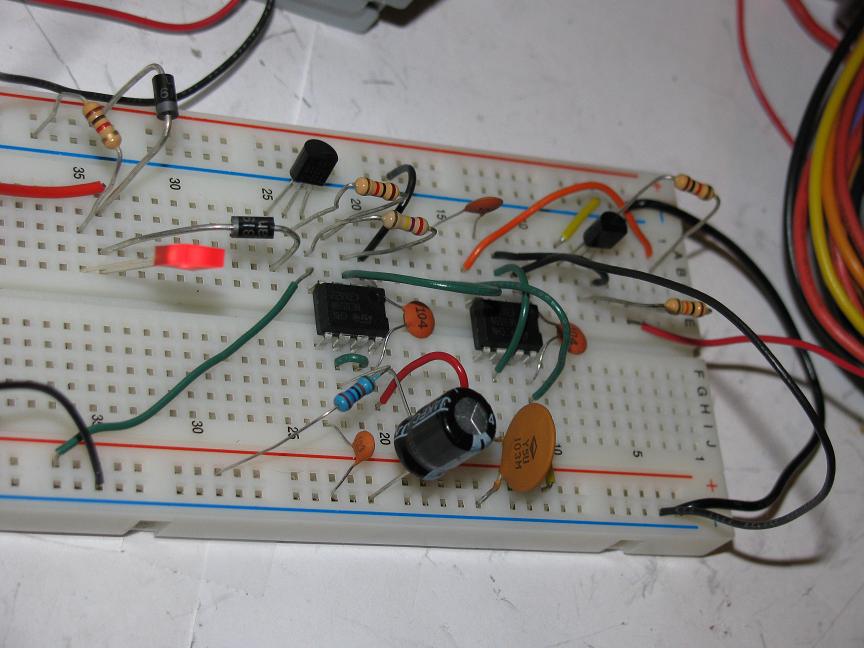
Right now it's running from a breadboard, but hopefully I'll be able to assemble it onto a PCB and install it into a power supply. I priced everything out on digikey - the total comes to $4.13, not including a circuit board. Then you'll have 10 resistors left over (minimum order quantity is 5).
Here's a picture of it built on the breadboard. The LED is there so I don't have to sit there with my hand over the fan to see if it's on or not. It's not in the schematic.
It took me 8 hours to get this working....mostly because I soldered a wire in bad to begin with, and I kept hooking the power up to the 555 timers backwards....but it's nice to have it working What does everybody think?
Here is the schematic:
The little "V+" things that look like umbrellas are all linked to the +5vsb, I used them to avoid cluttering it up.
It uses two 555 timers, a 2N2222A transistor and a 2N3904 transistor. One change though from the schematic, for D1 and D2 I used 1N5819 schottky diodes, so there'd be less voltage loss. My EAGLE libraries don't have that part though. I tried to make many of the component values the same to minimize the number of different parts. R2 and C5 control the length of time the fan runs after you power down - with these values it runs between 2 and 2.5 minutes. I know there are probably better, more efficient ways to do this, but I used the parts I have on hand. I know that PSU fans are 12 volt, and some won't run on only 5 volts, but this runs then at 12 volts (minus the diode voltage drop) until the PSU turns off, and then the 5 volts kicks in. Withe the two fans I tested this on (one 80mm and one 120mm) the 5 was enough to keep them spinning.
It uses the +5v rail to detect whether or not the power supply is on or not. The 3904 and IC2 are there to take this slowly falling signal (because of the capacitors) and make it a short instantaneous drop, so that it triggers IC1. The +12v connection is there to power the fan when the PSU is on. The diodes protect the other parts of the circuit from voltages that aren't supposed to be there.
I used a 0.6ohm resistor to measure the current draw of the circuit. With the PSU on and the fan running off of 12v, the circuit uses about 10mA from the +5vsb. With the PSU off and the fan running off the +5vsb, it draws about 40-45mA, depending on the fan and stuff. With the PSU off and the fan off (after the 2 minutes) the current draw is about 8mA. So, you don't have to worry about it hogging all your stand by power if it's running.
Right now it's running from a breadboard, but hopefully I'll be able to assemble it onto a PCB and install it into a power supply. I priced everything out on digikey - the total comes to $4.13, not including a circuit board. Then you'll have 10 resistors left over (minimum order quantity is 5).
Here's a picture of it built on the breadboard. The LED is there so I don't have to sit there with my hand over the fan to see if it's on or not. It's not in the schematic.
It took me 8 hours to get this working....mostly because I soldered a wire in bad to begin with, and I kept hooking the power up to the 555 timers backwards....but it's nice to have it working
Attached Files
if you find these attachements useful please consider making a small donation to the site


Comment