Improving a cheap, crappy power supply

Collapse
X
 
  • Time
  • Show
Clear All
new posts
  • mariushm
    Badcaps Legend
    • May 2011
    • 3799

    #1

    Improving a cheap, crappy power supply

    Here's the deal.

    I posted this power supply in the psu discussion thread a while ago, it was in my sister's computer.. a Premier 400w psu:


    I realize it never will do 400w, maybe won't even do 200w as it is.
    It's currently sitting in my workbench pc, which is a cheap Sempron so it's unlikely it will even go over 100 watts.

    I'm thinking it could be decent 150-200w power supply if make some modifications to it.
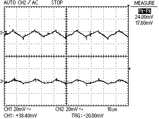
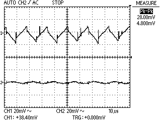
    As it is right now, it has the two diode treatment for 12v, missing inductors for pi filter, small output capacitors, small input capacitors (fake uF value, only 220uF).

    I have the power supply that failed in my father's computer, which is this one presented here:

    https://www.badcaps.net/forum/showth...561#post400561

    If you don't feel like clicking on other pages, here's a summary:


    This one's even lousier, but I could transfer the input capacitors and replace the diodes on 12v with the actual diode pair chip (16a rated) and maybe also replace the diode pair for 3.3v (rated for 10a) with the second diode pair rated for 16a.

    So this would be a first.

    Now, I'd also like to add inductors and second capacitors just to smooth out the output a bit. Of course I'll increase the output capacitors a bit, maybe go with 1500-2200uF instead of 1000uF that's now installed.

    But I did some cleaning recently and trashed a lot of broken power supplies, so now the only donor boards I still have are some old AT ones that were rated for 150-250w :

    (continued in next post due to exceeding the image count)
    Attached Files
    Last edited by mariushm; 01-08-2014, 10:44 PM.
  • mariushm
    Badcaps Legend
    • May 2011
    • 3799

    #2
    Re: Improving a cheap, crappy power supply


    This was an old 150-200w psu from a Siemens Nixdorf PC ( pentium 90, 16 edo ram etc) ... so about 1990 vintage.

    There's only one inductor and it's small so I don't think it would be suitable but I'm thinking if I should re-use the Cx and Cy capacitors. It's a really old power supply though, they could already be somewhat damaged... is it more dangerous than the benefits I wonder?


    This was from a 250w (on label) atx psu. Used the heatsinks for a project.

    This board has some inductors and they seem OK size wise, but I never really bothered to study how large inductors have to be, how much other parameters like resonance frequency, peak current etc matter...

    I'd like to ask, what are the risks if these inductors are undersized or in some ways not suitable for the power supply?

    If I get some improvements with the inductors and replacements I mentioned in previous post, I was thinking if it's worth replacing the primary rectifer diodes and maybe the 5vSB diode with some ultra fast 800v/3a UF3006 diodes.
    It's not like I'm going to use the power supply for anything serious, but hey, as long as I have it open...
    Attached Files
    Last edited by mariushm; 01-08-2014, 10:44 PM.

    Comment

    • kaboom
      "Oh, Grouchy!"
      • Jan 2011
      • 2507
      • USA

      #3
      Re: Improving a cheap, crappy power supply

      Except for the Magnetek, all that stuff's junk. Well, the Magnetek is too, since you "borrowed" its parts. That was the one you should've saved...

      No heatsinks to speak of. Tiny output wires, with voltage drop "compensated" by a 3.3 sense, isn't going to cut it. Nearly no output filtering, no line filter- enjoy the RFI wiping out your radios.

      The worst of your problems isn't the "four diode treatment."
      "pokemon go... to hell!"

      EOL it...
      Originally posted by shango066
      All style and no substance.
      Originally posted by smashstuff30
      guilty,guilty,guilty,guilty!
      guilty of being cheap-made!

      Comment

      • mariushm
        Badcaps Legend
        • May 2011
        • 3799

        #4
        Re: Improving a cheap, crappy power supply

        I know. Let's just call it polishing a turd, a side project... like I said it's not going to be used for anything serious.

        Add output filtering, add line filters, replace the diodes on the 12v rail etc.. maybe more.

        Comment

        • cheapie
          null
          • Jul 2010
          • 849
          • USA

          #5
          Re: Improving a cheap, crappy power supply

          Huh, didn't know Magnetek made that stuff. I thought they just made motor drives and stuff.

          Comment

          • goodpsusearch
            Badcaps Legend
            • Oct 2009
            • 2850
            • Greece

            #6
            Re: Improving a cheap, crappy power supply

            Why you trashed psus in the first place? They are great sources for parts for projects like this. I have more than 15 dead psus in the basement that I regularly pick stuff from them.

            Comment

            • mariushm
              Badcaps Legend
              • May 2011
              • 3799

              #7
              Re: Improving a cheap, crappy power supply

              I don't repair electronics for a living so I don't have an "office" or some place to store parts, and I don't have a volume of repairs big enough to justify keeping a bunch of broken power supplies around.

              I'm living alone in a small rented apartment (no basement, just a closed balcony where I keep some stuff like cfl tubes for monitors, some faulty motherboards etc) and all the broken stuff was starting to take up a lot of space.

              Comment

              • Pentium4
                CapXon Be Gone
                • Sep 2011
                • 3741
                • USA

                #8
                Re: Improving a cheap, crappy power supply

                Kudos for doing that. It isn't time or cost effective to improve these crap power supplies but it sure it fun! and they can become plenty reliable, more so than a modern design that uses Asia X/CapXon caps, etc. (In my opinion...) I did one this week that I might make a thread on.

                The one that was in yours dad's computer has potential. It has IC for 5VSB, and the main toroid is better than most of the PSU's in its category. The transformer looks small but I bet it'd do 250W since you're on 230V, not that I'd trust those heatsinks for that continuously though.

                Comment

                • TELVM
                  Badcaps Veteran
                  • Oct 2012
                  • 547
                  • Spain

                  #9
                  Re: Improving a cheap, crappy power supply

                  If it helps the L&C I restored works like a charm, with decent voltage regulation across all the envelope (as far as a MMF can tell).

                  I lack scope and can't tell about ripple & noise, but provided the Deer/Allied/L&C in cuestion came with decent PI coils (or we add them) they should behave:


                  With real caps, good cooling and some extra improvements they can power low draw comps decently.

                  Comment

                  • mariushm
                    Badcaps Legend
                    • May 2011
                    • 3799

                    #10
                    Re: Improving a cheap, crappy power supply

                    I had some spare time today to make some preliminary tests.

                    Put the constant current load on 5v to about 0.8 amps and a 20w lightbulb on 12v and tested the output with the oscilloscope:

                    3.3v no load (3.347v), 5v @ ~0.8a (5.085v), 12v @ ~ 20w (12.076 at start, 12.085v as it warmed up, after about 20 minutes)


                    Now keep in mind this is by no means scientific as in I didn't try to minimize as most as possible the ground lead on the probe, no 10uF at the tip of the probe, atx case open etc so yeah, doesn't matter that much.

                    The voltage ripple is reasonable, once there's some load. Without load on 12v, the 12v went up to 12.35v

                    The primary capacitors on both power supply are fake, both say 330uF but they're actually 220uF.
                    The ones on this psu I want to improve are the YC brand, and the capacitance is about the same on both, with ESR also good on both:


                    The ones on the "donor" power supply are larger in diameter and they're rated for 105c compared to the 85c YC capacitors, but one shows as 247uF and the other at 228uF.


                    Honestly, I "trust" the YC capacitors more than these TS ones and I'll probably leave them in the original power supply.

                    I then went and tested the TO-220 diode pairs on the donor power supply, the one that failed in my father's computer because I had a feeling at least one of them was shorted ... tested with the multimeter and had 330 ohm on 12v (the bleeder resistor), 0.26 ohm on 5v and something similar on 3.3v

                    The 16fo20c that's probably on the 12v tested OK, about 0.48v drop on both diodes.
                    One of the 16s45 chips had a shorted diode in them.. it was probably the 5v one but I can't be 100% sure as I desoldered all three at same time.
                    The other 16s45 tests fine, 0.17v drop on both diodes inside.
                    Now the 5v output measures about 20 ohm on the resistance, which is probably the bleeder resistor for the secondary capacitors.

                    Next, the plan is to use the extra spaces for wires on 5v and 12v to add a couple of sata cables from the donor board to the new psu because the original board has no sata connectors.
                    Then, I'll probably replace the existing 1000uF capacitors with 2200uF ones just to see if and how much the voltage ripple improves just by replacing capacitors.

                    Then, I'll try to add inductors for the pi filter on 5v and 12v - I recycled an inductor used on 5v on one of those power supplies from the second post.

                    Still not sure if the inductor value is really important for these crappy power supplies. I suspect it's not really that important. I have an inductor meter and I'll measure them before inserting them in the power supply.
                    Attached Files
                    Last edited by mariushm; 01-13-2014, 01:14 PM.

                    Comment

                    • TELVM
                      Badcaps Veteran
                      • Oct 2012
                      • 547
                      • Spain

                      #11
                      Re: Improving a cheap, crappy power supply

                      Good stuff Mariushm . I envy your toys .

                      Will be very interesting to see how bigger uF caps then retrofitted PI coils influence ripple .

                      Comment

                      • goodpsusearch
                        Badcaps Legend
                        • Oct 2009
                        • 2850
                        • Greece

                        #12
                        Re: Improving a cheap, crappy power supply

                        Where did you get an inductor meter????

                        Comment

                        • mariushm
                          Badcaps Legend
                          • May 2011
                          • 3799

                          #13
                          Re: Improving a cheap, crappy power supply

                          Uni-T UT602:

                          http://dx.com/p/uni-t-ut602-2-6-lcd-...-1-x-9v-173362

                          Bought from DinoDirect, not DX, but both are good sources for it.

                          It's an LR meter, not a LCR meter. It only has Resistance, Diode, Inductor and Transistor testing, Capacitance is missing. But I have an esr meter and capacitance function on the UT61E, it's good enough for my needs..

                          Uni-T UT603 is about 7-8$ more expensive and adds capacitance to the functions, that's the only difference.

                          It works for me but it kind of sucks in a way because it's manual ranging only, and has a poor way of telling the inductor is too big for that range. You don't get an OL or 1 when out of range.

                          You have to guess how much an inductor should be and select the closest range, then move up to next range just to see if the meter will show the same value (if value changes, then the value on previous range was overload/maximum value possible on that range).
                          Alternatively, just go on the smallest range and keep moving to higher ranges until the value doesn't change. So it works, but it wastes time when measuring.

                          Comment

                          • momaka
                            master hoarder
                            • May 2008
                            • 12175
                            • Bulgaria

                            #14
                            Re: Improving a cheap, crappy power supply

                            Originally posted by mariushm
                            Then, I'll probably replace the existing 1000uF capacitors with 2200uF ones just to see if and how much the voltage ripple improves just by replacing capacitors.

                            Then, I'll try to add inductors for the pi filter on 5v and 12v - I recycled an inductor used on 5v on one of those power supplies from the second post.
                            I'd do these two things before doing anything else. Without the PI coils and larger capacitors, the ripple output will be crappy.

                            I would also suggest you "shuffle around" or replace those dummy load/bleeder resistors. Nothing lower than 22 Ohms for 3.3V rail, 47 Ohms for 5V rail, and 270 Ohms on 12V rail. Otherwise, you are just wasting power and heating/cooking your caps unnecessarily.

                            Lastly, make sure to change the small critical cap on the 5VSB with something good.

                            Originally posted by mariushm
                            Still not sure if the inductor value is really important for these crappy power supplies. I suspect it's not really that important.
                            For the small PI coils, it's not. Most are in the ballpark from 0.5 to a few uH, which IIRC is small compared to the mail toroid. The ones from the 250W PSU should be fine.

                            Also, try to build the PSU around the PC it will be powering... i.e. if the PC draws power for the CPU from the 5V rail, then focus on improving the 5V rail the most and make sure it has the biggest possible rectifier (even a 20A would be kind of wimpy here). If it's the 12V rail, then make sure to improve the 12V rail rectifier.
                            Last edited by momaka; 01-13-2014, 06:37 PM.

                            Comment

                            • mariushm
                              Badcaps Legend
                              • May 2011
                              • 3799

                              #15
                              Re: Improving a cheap, crappy power supply

                              Another update.

                              Here's how the power supply looks now:

                              Top view:


                              Side view:


                              Measured the two inductors and they're both around 12-15uH. Had to use the dremel to thin the leads a bit but they eventually got in. They're on the 5v and 12v rails.

                              Replaced the two diodes (FR302, 3A each, 70v max, fast recovery) that were driving the 12v with the 16s45 recovered from the psu that died in my father's computer. That one's 16a 45v and so on. Originally the diodes weren't insulated from the heatsink, but I insulated the to-220 package just because I could.

                              470uF 16c Yc capacitor (TK) changed to 1000uF 16v Panasonic FM (12v rail, before inductor, stuck to 1000uF due to diameter and because it's probably more than enough already)
                              1000uF 16v G-LUXON LG changed to 3300uF 16v NCC KZE series (12v rail, after inductor)

                              2 x Su'scon 1000uF 10v changed to 2 x 2200uF 6.3v Panasonic FM (5v rail, before and after inductor)

                              Left the 470uF 10v capacitor where it is, it's for the -5v rail.. Not important enough to care.
                              Empty capacitor space by the 12v to-220 diode is probably for the 3.3v. Wasn't populated, probably going to put a 470-1000uF 10-16v on it.

                              3.357v, 5.095v, 12.179v <- no load
                              3.351v, 5.005v, 12.574v <- just 5v @ 0.8a load
                              3.351v, 5.037v, 12.379v <-5v @ 0.8a , 20w light bulb on 12v

                              scope pictures with both 5v and 12v loaded as above (same as test in previous post for consistency).

                              3.3v / 5v / 12v


                              Picture quality kinda sucks because i turned off lights near the desk so that transformer in the lamp won't affect the scope.

                              Anyway, quite an improvement as you can see from the scope pictures. Now of course, the load i tested with is very small but it should be better at higher loads compared to how it was before.
                              Attached Files

                              Comment

                              • TELVM
                                Badcaps Veteran
                                • Oct 2012
                                • 547
                                • Spain

                                #16
                                Re: Improving a cheap, crappy power supply


                                As you say a noticeable improvement @ low loads, that should get even better @ higher loads .


                                Seems the output cap distribution in your PCB is different from my LC.
                                Attached Files

                                Comment

                                • Pentium4
                                  CapXon Be Gone
                                  • Sep 2011
                                  • 3741
                                  • USA

                                  #17
                                  Re: Improving a cheap, crappy power supply

                                  Nice! It looks good, and will look great with input filtering. I'd replace the caps between the switchers, I've seen a lot of them fail or nearly fail in those older Deer PSU's. Did you re-oil the fan?

                                  Comment

                                  Related Topics

                                  Collapse

                                  • sam_sam_sam
                                    Mitsubishi CNC switching power supply board dead / relay board bad diode failure
                                    by sam_sam_sam
                                    I was working on this CNC machine today found no keyboard functioning no control relay powering on
                                    The screen powered on and was giving an operation error but the manual was not very clear about what the error exactly was but with a little bit of troubleshooting and finding out that the control relays not powering on and no keyboard functions we narrowed down to this one switching power supply which of course does not have any indicator LED light they are on the keyboard interface/relay controller board

                                    Found shorted diodes on main controller relays there are 3 of them that...
                                    01-07-2023, 05:43 PM
                                  • sam_sam_sam
                                    12 volt switching power supply modification to 14.5 volts before blocking diode add
                                    by sam_sam_sam
                                    I saw this switching power supply on eBay and wanted to see if could be modified to run 14.5 volts before the blocking diode was add and this switching power supply seems to have no issues doing this

                                    I did recap the switching power supply except the the main filtering capacitors and I managed to break the selector switch for the voltage setting but just jumped it

                                    One note I used 25 volt capacitors on the output side of this power supply because they used 16 volt capacitors and because I am running the voltage up a little bit higher 12 volts to 14.5 volts there would...
                                    04-11-2021, 11:01 AM
                                  • Tnmg
                                    Sony XBR-65X850E power supply board diode replacement
                                    by Tnmg
                                    I have a Sony XBR-65X850E that when plugged in buzzes for a few seconds about 5-7 times but the screen never comes on. It looks like one of the four diodes on the main power supply board are bad. I'd like to replace all four at the same time. The diodes that are bad are the D750, D751, D752 and D753. The S750 looks discolored and fails the diode test on the board. It hasn't been removed from the board yet for testing.

                                    Are all four of these the same diode? I saw a video that called the discolored one a Schottky 5150 diode. How can I make sure to get the right diodes for these?...
                                    07-01-2022, 04:54 PM
                                  • pcardoso73
                                    iMac power supply short-circuit diode to ground
                                    by pcardoso73
                                    Hi,
                                    I have an iMac with the power supply reference: ADP-200DFB.

                                    This power supply is not working and when trying to debug the problem with a multimeter, I found what I thought to be a short circuited diode (the short-circuit is to ground).

                                    With the continuity test it beeps both ways, so doesn't block current flow at all then reverse biased. But after removing the diode the beep continues and the diode seems healthy. It seems to exist a real short-circuit.

                                    As I have another ADP-200DFB power supply (faulty one as well), I have checked the same...
                                    06-09-2020, 08:47 AM
                                  • JimBanville
                                    Definitive technology SC 2000 subwoofer amp's power supply clicking and popping
                                    by JimBanville
                                    The sub developed a constant popping every couple seconds from woofer and power LED flickering with nothing but wall AC connected. Connecting an audio cable didn't change anything. It doesn't play but a second or two of audio in between the pops.
                                    Opened it up and discovered the power supply is making a faint clicking or ticking sound.
                                    I measured the amp's output to the woofer and it pulses up to 50mv DC to be driver. The pulses coincide with the power supply ticking/clicking.
                                    I measured the power supply output going to the amp board and it too has this pulsing. Voltage cycles...
                                    09-13-2023, 07:21 AM
                                  • Loading...
                                  • No more items.
                                  Working...