
Hello,
Have a Samsung 2233SN with no CFL backlight. Testing with a flashlight, I can see the image is displayed, but the backlight fails after some seconds.
Sometimes, after being off for a while, the backlight will remain on for a couple minutes, but most of the times it fails immediately.
I tried to follow the guide present in this forum, but so far I haven't de-soldered any components. I need some advice on how to proceed to diagnose this display.
Following the guide I tested the following:
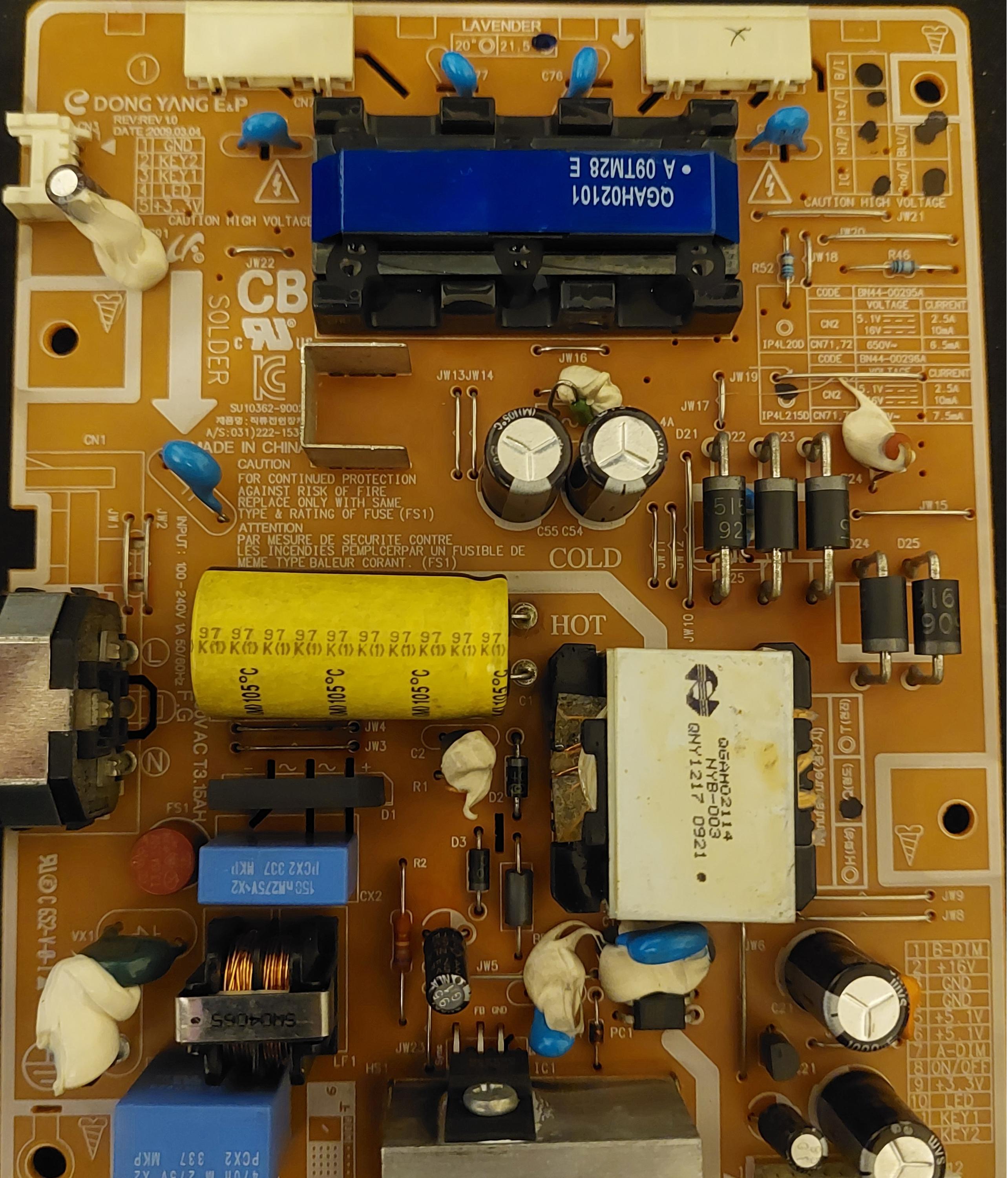
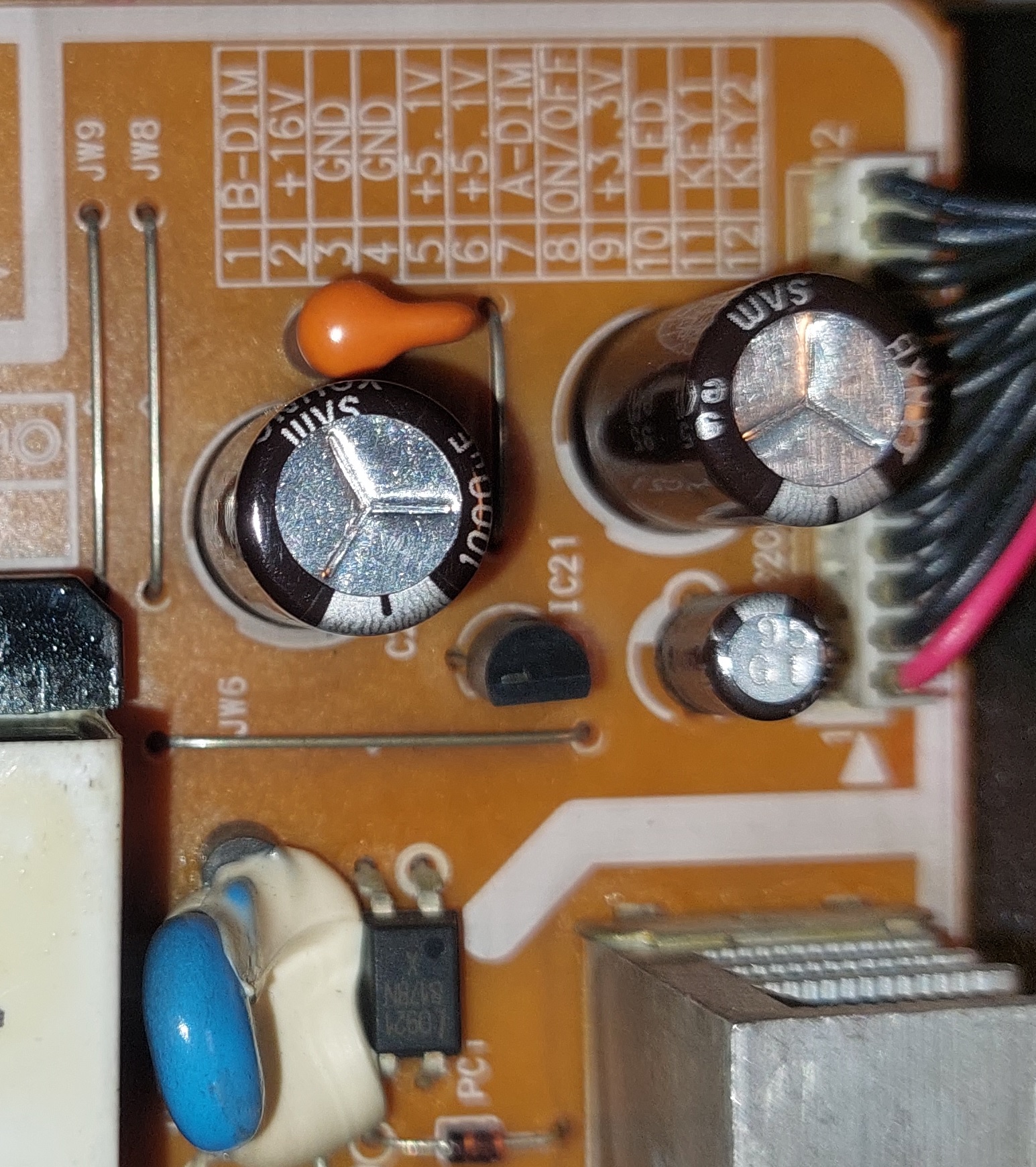
The transformer for the CFL: Between primary and secondary windings I get OL. I measure 1.14KΩ across both secondary windings. The weird part is that I measure 0.3 Ω between one of the primary windings, and 3 MΩ in the other primary winding. I added a image, where I marked in blue the pins I used to measure the secondary windings, and the pings I used to measure the primary windings.

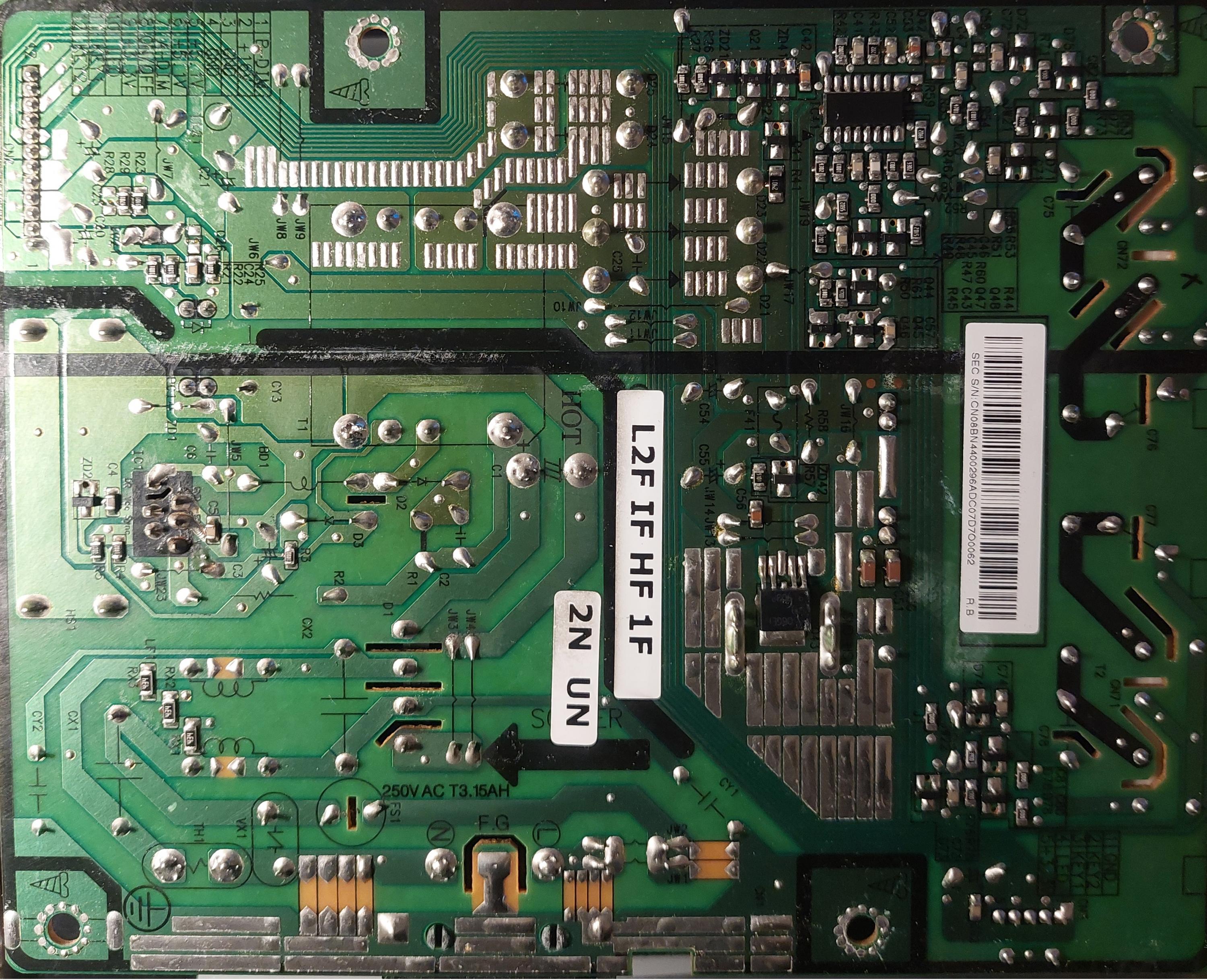
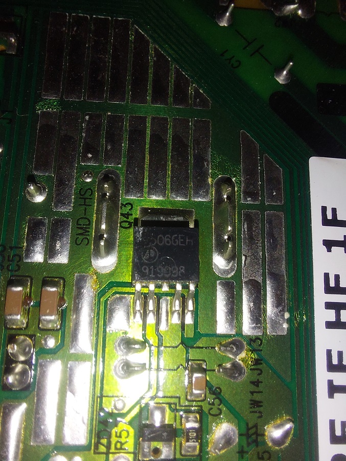
The MOSFET, I noticed a AP4506GEH on the bottow of the board, which I believe is used to drive the transformer for the CFL.
Across pins 1 and 2 I got: 29.7 KΩ (same, if I invert the multimeter leads)
Pins 3 and 4: 5.1 KΩ (same, if I invert the multimeter leads)
Between any of the pins, and the "tab" at the top, I get a reading in the Mega ohms range that keeps changing, increasing slightly.
It doesn't appear to be shorted.
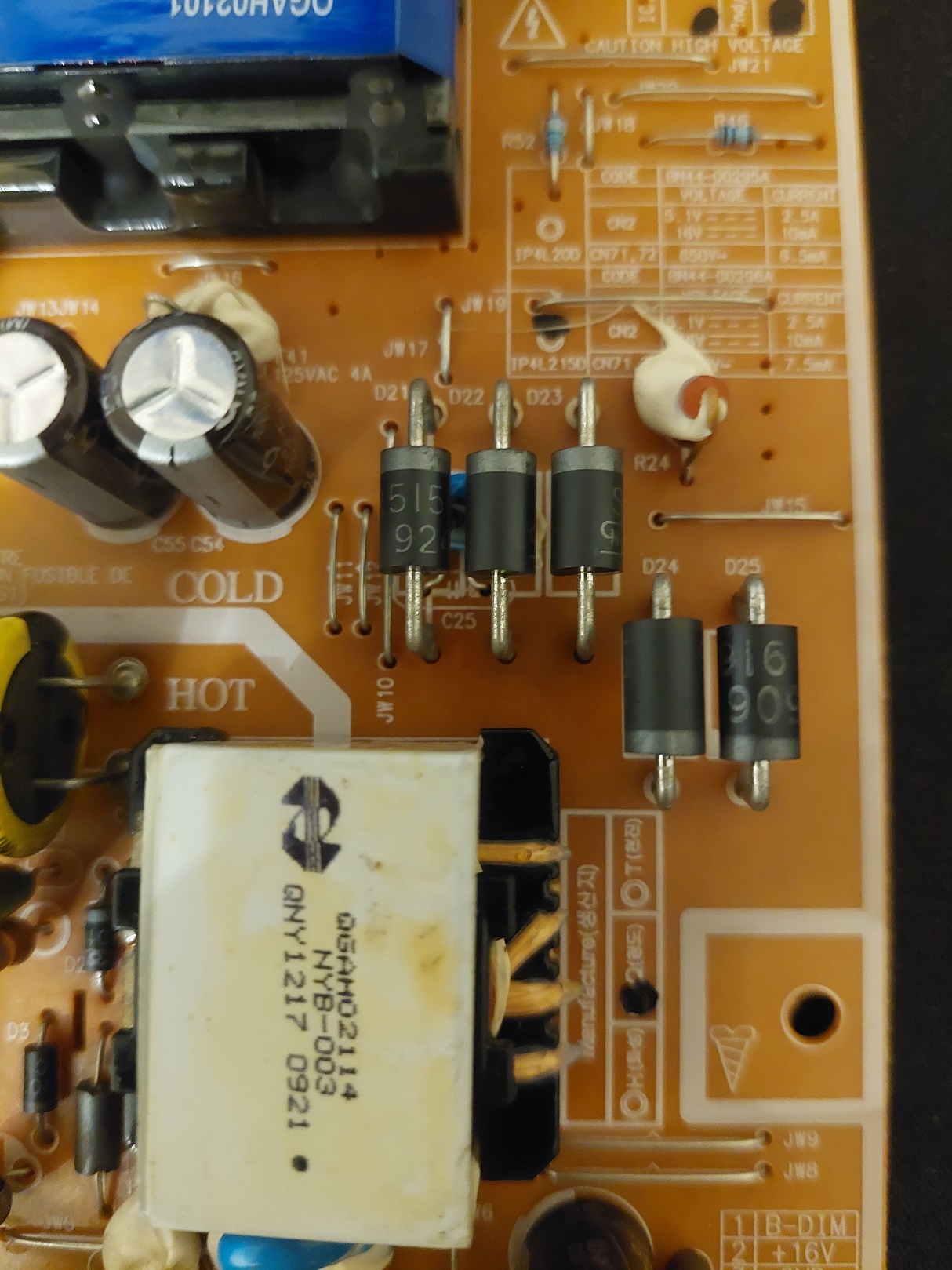
The Diodes, I think I will have to remove the diodes to test them.
D21, D22 and D23 are reading 0,282 V. In the non conductive direction, the reading starts at 0 V and increases until OL.
D24 and D25 are reading 0,167 V. In the non conductive direction they start at 0 V and goes up to 2.67 V.
Testing the 12 PIN connection the 16V pins had close to 19V. I am not sure if that could be consider normal, or if that value is miss printed.
What should be my next step? remove the caps to test them? I can see 7 electrolytic caps in the board, plus the main big filtering cap. I believe only 2 of them are related to the CFL backlight.
Look at the reading I got, are those readings in the transformer windings normal? I would expect them to be the same, but it was measured in circuit.
Have a Samsung 2233SN with no CFL backlight. Testing with a flashlight, I can see the image is displayed, but the backlight fails after some seconds.
Sometimes, after being off for a while, the backlight will remain on for a couple minutes, but most of the times it fails immediately.
I tried to follow the guide present in this forum, but so far I haven't de-soldered any components. I need some advice on how to proceed to diagnose this display.
Following the guide I tested the following:
The transformer for the CFL: Between primary and secondary windings I get OL. I measure 1.14KΩ across both secondary windings. The weird part is that I measure 0.3 Ω between one of the primary windings, and 3 MΩ in the other primary winding. I added a image, where I marked in blue the pins I used to measure the secondary windings, and the pings I used to measure the primary windings.
The MOSFET, I noticed a AP4506GEH on the bottow of the board, which I believe is used to drive the transformer for the CFL.
Across pins 1 and 2 I got: 29.7 KΩ (same, if I invert the multimeter leads)
Pins 3 and 4: 5.1 KΩ (same, if I invert the multimeter leads)
Between any of the pins, and the "tab" at the top, I get a reading in the Mega ohms range that keeps changing, increasing slightly.
It doesn't appear to be shorted.
The Diodes, I think I will have to remove the diodes to test them.
D21, D22 and D23 are reading 0,282 V. In the non conductive direction, the reading starts at 0 V and increases until OL.
D24 and D25 are reading 0,167 V. In the non conductive direction they start at 0 V and goes up to 2.67 V.
Testing the 12 PIN connection the 16V pins had close to 19V. I am not sure if that could be consider normal, or if that value is miss printed.
What should be my next step? remove the caps to test them? I can see 7 electrolytic caps in the board, plus the main big filtering cap. I believe only 2 of them are related to the CFL backlight.
Look at the reading I got, are those readings in the transformer windings normal? I would expect them to be the same, but it was measured in circuit.
Attached Files
if you find these attachements useful please consider making a small donation to the site


Comment