Oscillator repair? What kind of oscillator?

Collapse
X
 
  • Time
  • Show
Clear All
new posts
  • eccerr0r
    Solder Sloth
    • Nov 2012
    • 8687
    • USA

    #1

    Oscillator repair? What kind of oscillator?

    I have this broken oscillator, it should be 11Hz to 110KHz, but it doesn't seem to work properly, the output is really "noisy" - Something seems to have gotten open circuit.

    Bad capacitor for sure, or perhaps an open circuit somewhere. However this seems to be a homemade unit, so not sure if there's data available anywhere.

    So I did a partial circuit extract to figure out how this works, to find out whether or not this should be generating a sine wave generator as that could be useful (though a square wave is fine too). As I started drawing the schematic, I was kind of baffled by it: What kind of oscillator, and why is it built this way?

    This looks like a multivibrator oscillator, using a zener diode to keep voltage constant to maintain a bit of frequency stability.


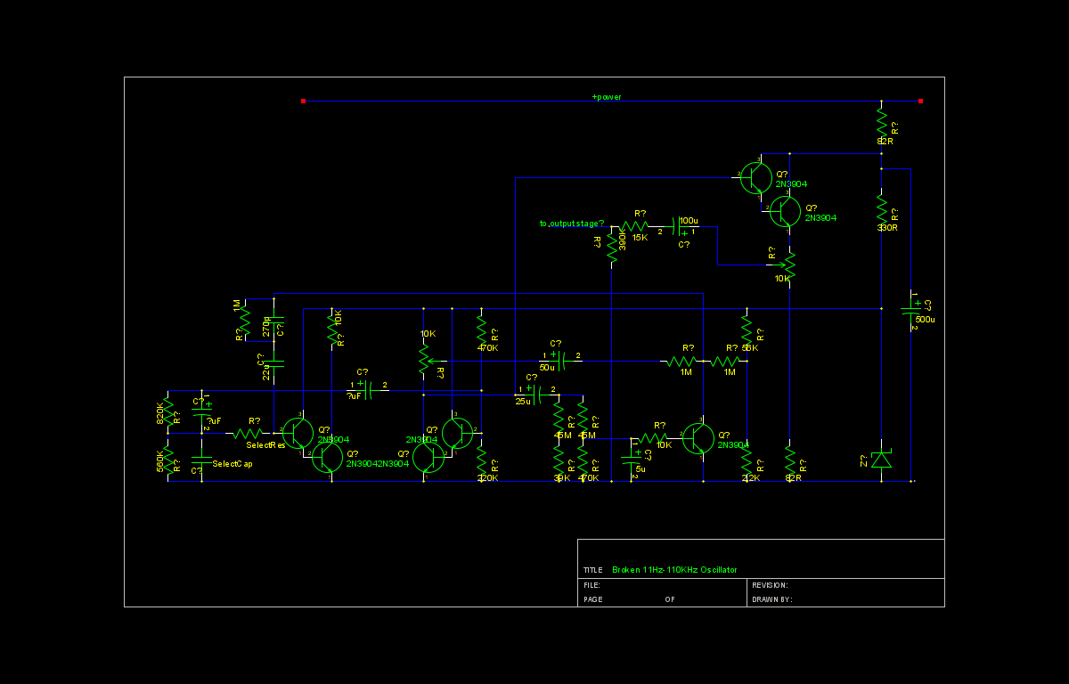
    I'm sure I have a lot of extraction errors here, as this was a vectorboard homemade unit and thus a bit tougher ("virtual" multilayer). Any comments about this circuit (It's not complete, but has the oscillating portion. An oscilloscope attached to this portion of the circuit exhibits the same problem as the output, so the output stage looks OK...

    Note: It uses 2N3393 transistors, not 2N3904s...

    Any ideas? I'm wondering if I should just junk this circuit and replace it with a few op amps...
    Attached Files
  • stj
    Great Sage 齊天大聖
    • Dec 2009
    • 30956
    • Albion

    #2
    Re: Oscillator repair? What kind of oscillator?

    it will take me a while to see that - what the hell is with the colour choice!

    go download eaglecad.

    Comment

    • stj
      Great Sage 齊天大聖
      • Dec 2009
      • 30956
      • Albion

      #3
      Re: Oscillator repair? What kind of oscillator?

      i can understand that, but there is a lot of feedback going on - any cap problems will probably be very problematic.

      Comment

      • eccerr0r
        Solder Sloth
        • Nov 2012
        • 8687
        • USA

        #4
        Re: Oscillator repair? What kind of oscillator?

        Not sure why it didn't do the usual black on white... alas, it's just gschem, part of gEDA. Looks fine on my screen, alas I normally use a black background for most things (leftover from CRT days)

        Not sure why the multivibrator, or is it just that - the 5 transistors along the bottom are the oscillator, the one on top just looks like a follower amp. Why it (and others) are hooked up in Darlington mode I don't know. The single transistor on the rigth-bottom I'll need to look for a pullup somewhere, it does look like in common emitter form but nothing pulling it up to vcc...

        Comment

        • Longbow
          Badcaps Veteran
          • Jun 2011
          • 623
          • USA

          #5
          Re: Oscillator repair? What kind of oscillator?

          I cannot tell from your words if this is your circuit design. But since it looks unique, I'll assume that it is. A fresh schematic might help and a brief description of why you made the choices that you did. I have never seen darlington connected transistors used like this. Was this device meant to be a Wien bridge oscillator? There is no obvious signal output and much unnecessary duplication of parts.
          Is it plugged in?

          Comment

          • eccerr0r
            Solder Sloth
            • Nov 2012
            • 8687
            • USA

            #6
            Re: Oscillator repair? What kind of oscillator?

            I didn't design this circuit, else I'd have a complete schematic somewhere. Someone tossed it and I suppose I was the third person to get my hands on it. This was just a rough sketch of what I could hand extract from the circuit. Also note: it's not complete. The output stage "power amplifier" is omitted as I suspect if I can get the circuit to oscillate correct at the output of this first emitter follower stage, the rest can be easier to diagnose.

            I can't tell if this was supposed to be a Wien bridge or not, the connectivity looks really weird to me. The signal "output" is in the center of the schematic after the darlington emitter follower stage in the upper right of the schematic. I will need to check the select knobs and make sure it's not dual stage where it selects two resistors/capacitors for each detent...then it very well may be some sort of sinusoidal or Wien Bridge.

            I'd like to know what was going on in the designer's head too... Just baffling to me.

            This is an adjustable oscillator which is even weirder. The adjustable elements, R and C are towards the right/bottom. If the switches isn't actually a split select, then it would make it confusing as to how it could be (a) sinusoidal and (b) 50% duty cycle across all frequencies.

            Weeeeird!!!
            Last edited by eccerr0r; 09-03-2015, 06:12 PM.

            Comment

            • Longbow
              Badcaps Veteran
              • Jun 2011
              • 623
              • USA

              #7
              Re: Oscillator repair? What kind of oscillator?

              I agree that the whole thing is quite weird. There is no good reason to design such a thing with darlington transistors in the first place. If you are designing a Wien bridge, then you must have some form of feedback control which I do not see here. A discreet 2 transistor astable will give you a nice square wave with no more than 8 parts. These days you can have an astable and an output buffer with an inexpensive quad nand gate. Many times you will see a triangle wave basic oscillator (requiring a constant current source to charge a capacitor) followed by a group of hand picked shaping diodes to produce a near sine wave output. That approach is also not present here. I would scrap this thing and move on!
              Last edited by Longbow; 09-04-2015, 08:36 AM.
              Is it plugged in?

              Comment

              • budm
                Badcaps Legend
                • Feb 2010
                • 40746
                • USA

                #8
                Re: Oscillator repair? What kind of oscillator?

                The diagram does not look right at all, for example the two transistors on the left side hooked up as shown, the first transistor has Collector connected to the regulated B+ (regulated by the ZENER diode), the Emitter is connected to the BASE of the second transistor without any current limiter resistor for the BASE of the second transistor. When that first transistor is turned on it will wipe out the E-B junction of the second transistor. Same problem on the other two transistors on the right.
                Also on the second transistor, there is Collector resistor but nothing else is connected to the Collector, there is no junction dot on the Collector leg.
                I think the board should be retraced again for correct connections.
                Last edited by budm; 09-04-2015, 11:23 AM.
                Never stop learning
                Basic LCD TV and Monitor troubleshooting guides.
                http://www.badcaps.net/forum/showthr...956#post305956

                Voltage Regulator (LDO) testing:
                http://www.badcaps.net/forum/showthr...999#post300999

                Inverter testing using old CFL:
                http://www.badcaps.net/forum/showthr...er+testing+cfl

                Tear down pictures : Hit the ">" Show Albums and stories" on the left side
                http://s807.photobucket.com/user/budm/library/

                TV Factory reset codes listing:
                http://www.badcaps.net/forum/showthread.php?t=24809

                Comment

                • eccerr0r
                  Solder Sloth
                  • Nov 2012
                  • 8687
                  • USA

                  #9
                  Re: Oscillator repair? What kind of oscillator?

                  Yes I had noted that the "upper" transistor in each of the two "darlingtons" are connected funny and would short out the supply if turned on. I'll have to go check again and make sure but after double checking it (on that day I drew it) that's really what it looks like.

                  The collector load on the first "darlington" probably indeed should be connected to that capacitor that feeds back into the base of the second "darlington" or at least I think that was a mistake I did when I tried to beautify the schematic a bit (without disturbing the placement to schematic correlation too much).

                  Unfortunately indeed I'm sure I still have some extraction errors, but wondering if someone could notice some basic topology here to say whether this was intended to be some sort of sine wave generator versus a square wave...

                  If it indeed should have been a square wave (and yes, two transistors is sufficient to do this, not 5) yes I should just scrap this and make my own circuit, I can make square wave oscillators in my sleep, but getting a low distortion adjustable sine wave oscillator I can't (I'm no analog guy...) and it might be helpful to have a test instrument as such...

                  Comment

                  • budm
                    Badcaps Legend
                    • Feb 2010
                    • 40746
                    • USA

                    #10
                    Re: Oscillator repair? What kind of oscillator?

                    Simple filter turning Sq wave to Sine wave.
                    https://cdn.badcaps-static.com/pdfs/...39c4148b91.pdf
                    Sine wave oscillator:
                    https://cdn.badcaps-static.com/pdfs/...ce4db75dc0.pdf
                    https://cdn.badcaps-static.com/pdfs/...c9eb5c73ea.pdf

                    You can also look up App notes on OPAMP.
                    Tone generator using PC. i do not know what the requirement for your generator are.
                    http://www.audiocheck.net/audiofrequ...r_sinetone.php
                    Never stop learning
                    Basic LCD TV and Monitor troubleshooting guides.
                    http://www.badcaps.net/forum/showthr...956#post305956

                    Voltage Regulator (LDO) testing:
                    http://www.badcaps.net/forum/showthr...999#post300999

                    Inverter testing using old CFL:
                    http://www.badcaps.net/forum/showthr...er+testing+cfl

                    Tear down pictures : Hit the ">" Show Albums and stories" on the left side
                    http://s807.photobucket.com/user/budm/library/

                    TV Factory reset codes listing:
                    http://www.badcaps.net/forum/showthread.php?t=24809

                    Comment

                    • eccerr0r
                      Solder Sloth
                      • Nov 2012
                      • 8687
                      • USA

                      #11
                      Re: Oscillator repair? What kind of oscillator?

                      There's a problem with those versus the circuit at hand:
                      1. This is a variable frequency oscillator, so filters past the fundamental in the output stage won't work.
                      2. This design is all transistor, and it looks like they are common emitter and thus likely leaks a lot of current through the base... Trying to correlate this with op amp designs, well, wondering which is biasing (not necessarily needed for op amps) and which are for oscillation has been a pain. Also as far as I can tell, there's only one RC section. I need to double check this but as far as I can tell, there are only 3 wires going from the adjustable R and C selectors that go to the oscillator, making it hard to make a multiple section filter. The Wien Bridge is still possible however, but I haven't been able to conclude this for sure... I did notice a few wires that I haven't accounted for, but I only seem to see one set of C for each detent in the select switch...

                      [more info]
                      Yes this unit indeed fits well within the audio range. I just wanted something that wasn't dependent on the PC and ideally something that I don't have to worry about frying due to bad connections - thus ideally something I understand and can fix. Plus this thing theoretically should be able to generate 100KHz fundamental, and all the better if it can also generate a sine wave.
                      Last edited by eccerr0r; 09-04-2015, 04:31 PM.

                      Comment

                      • budm
                        Badcaps Legend
                        • Feb 2010
                        • 40746
                        • USA

                        #12
                        Re: Oscillator repair? What kind of oscillator?

                        Well, what is the requirement for the variable frequency range, the output level requirement, the output Z, the acceptable distortion level, etc.
                        'This design is all transistor, and it looks like they are common emitter and thus likely leaks a lot of current through the base..' So it had Emitter follower out put to get low output Z, I am sure you do not want to have direct couple output with no DC Blocking cap. As far as the Base current, you will always have base current to bias on the transistor and if you want low distortion, then will want Class A output.
                        The Wien Bridge will be a way to go. No matter what you use you still have to the math on the RC.
                        Looking at your diagram, I really do not see how it can get up to 100KHz range with the RC value.
                        Looking the 5th transistor at the bottom, it has at least 1M for the Collector and no DC bias for the BASE at all with lytics cap in the BASE circuit.
                        The Z out of the circuit is also very high. There should also be a filter cap in parallel with Zener diode.
                        I wonder who ever made never really finish the project. The B+ feeding the circuit is also makes no sense unless that is in very low Ohms range, it basically become Collector resistor for the output circuit.
                        You should upload the pictures of the board.
                        BTW, did you measure the frequency out out of the circuit?
                        Last edited by budm; 09-04-2015, 04:15 PM.
                        Never stop learning
                        Basic LCD TV and Monitor troubleshooting guides.
                        http://www.badcaps.net/forum/showthr...956#post305956

                        Voltage Regulator (LDO) testing:
                        http://www.badcaps.net/forum/showthr...999#post300999

                        Inverter testing using old CFL:
                        http://www.badcaps.net/forum/showthr...er+testing+cfl

                        Tear down pictures : Hit the ">" Show Albums and stories" on the left side
                        http://s807.photobucket.com/user/budm/library/

                        TV Factory reset codes listing:
                        http://www.badcaps.net/forum/showthread.php?t=24809

                        Comment

                        • eccerr0r
                          Solder Sloth
                          • Nov 2012
                          • 8687
                          • USA

                          #13
                          Re: Oscillator repair? What kind of oscillator?

                          Yeah looking at what I drew, that bottom/right transistor's LPF couldn't possibly make it feed back fast enough, that capacitor would kill everything. And since the circuit doesn't seem to work (except for some weak oscillation behavior occasionally that's very touch sensitive) it makes it hard to analyze.

                          I looked at the selector knobs again... This time, staring at it, it does look like a R+C and R || C configuration so this very well could be a Wien Bridge, however the two C's it selects are different though the two R's are the same (C2 = C1/10 but R2=2R1). This unfortunately would make a very gapped bandpass which would not make a very good oscillator in my opinion, but there's more to learn from this circuit...

                          That weird transistor on the lower right, after making some (I think...MAJOR) schematic corrections, it might be part of the automatic gain control? Maybe? And is it possible that just the leftmost two transistors are the oscilllator, the middle "darlington pair" is just a gain stage? This is still very weird.

                          Will upload a new schematic, Unfortunately the best contrast picture I can get out from gschem is encapsulated postscript and I need to convert this to a format that people can read...

                          Just as a warning to come: The two "45M" resistors are actually "anti-parallel" DIODES and not really resistors. I also think I have a first pass at the "SelectRes" and "SelectCap" network that are selected by the switches drawn... so new schematic coming...
                          Last edited by eccerr0r; 09-05-2015, 12:16 AM.

                          Comment

                          • budm
                            Badcaps Legend
                            • Feb 2010
                            • 40746
                            • USA

                            #14
                            Re: Oscillator repair? What kind of oscillator?

                            I would like to see good clear pictures of the board, without correct diagram it will be hard to know if the circuit will really work. So far it does not.
                            Never stop learning
                            Basic LCD TV and Monitor troubleshooting guides.
                            http://www.badcaps.net/forum/showthr...956#post305956

                            Voltage Regulator (LDO) testing:
                            http://www.badcaps.net/forum/showthr...999#post300999

                            Inverter testing using old CFL:
                            http://www.badcaps.net/forum/showthr...er+testing+cfl

                            Tear down pictures : Hit the ">" Show Albums and stories" on the left side
                            http://s807.photobucket.com/user/budm/library/

                            TV Factory reset codes listing:
                            http://www.badcaps.net/forum/showthread.php?t=24809

                            Comment

                            • keeney123
                              Lauren
                              • Sep 2014
                              • 2536
                              • United States

                              #15
                              Re: Oscillator repair? What kind of oscillator?

                              design is all transistor, and it looks like they are common emitter and thus likely leaks a lot of current through the base... Trying to correlate this with op amp designs, well, wondering which is biasing (not necessarily needed for op amps) and which are for oscillation has been a pain. Also as far as I can tell, there's only one RC section. I need to double check this but as far as I can tell, there are only 3 wires going from the adjustable R and C selectors that go to the oscillator, making it hard to make a multiple section filter. The Wien Bridge is still possible however, but I haven't been able to conclude this for sure... I did notice a few wires that I haven't accounted for, but I only seem to see one set of C for each detent in the select switch...

                              The common emitter was used back in the day, 1980, for speed, up to 100 MZ. They require much more power then common collector. They used these for particle physics to capture events. Noise is a big problem with TTL and the faster one goes the greater the problem. I had to purchase power supplies for these circuits. Each supply was rated for 5 Volts at 200 amps. General Electric sold them.

                              Comment

                              Related Topics

                              Collapse

                              • Keshenatech1
                                Question on microprocessor crystal oscillator circuit
                                by Keshenatech1
                                I'm troubleshooting a reel controller board for an IGT slot machine. The digital section seems to be dead. There is no USB communication, PC or utility program for flashing firmware do not see it but they do see good/working boards. I noticed the waveform on the crystal is very erratic/asymmetrical/glitchy on the bad one compared to the nice even waveform on a good board. My question is would this most likely be caused by a bad crystal or something gone bad in the circuit loading it down? I'm attaching a couple pictures of my scope probing the good and bad boads.
                                02-26-2024, 11:05 AM
                              • Astonished
                                Fixing the Charge Circuit of the Batteries of the DC Motor
                                by Astonished
                                Hi friends of electronics

                                What you see in the video and pictures attached is the circuit for charging the batteries of a DC motor.

                                The problem is that this circuit cannot charge the batteries (3 1800mAH NiMH batteries) any more. When the circuit was OK, its green LEDs lit up one at a time to show that the batteries have charged more. But now that the circuit is flawed, LEDs light up as you see in the video and at the same time successive beeps are heard.

                                Please help me fix this circuit.

                                (the datasheet of the IC: https://pdf.datasheet.live/28...
                                01-28-2025, 06:24 AM
                              • Tarot Superstars
                                Short Circuit tester
                                by Tarot Superstars
                                Hello.
                                I have seen a short circuit tester made with 3 * 9V batteries, a voltage limiter component and a resistor connected to the probes of a multimeter.
                                The theory is that the meter becomes sensitive enough to read very low resistances and the lowest resistance to ground on a circuit is likely to be a short circuit in that area.

                                Link
                                The Amazing $1 Short Finder Upgraded! Convert ... - YouTube
                                https://www.youtube.com/watch?v=0eixDdCpiO4

                                My multimeter isn't normally sensitive to very small resistance, but when I put a 1 mega ohm resistor...
                                09-25-2023, 09:11 AM
                              • M1NEBLANK SHOW
                                MSI B250 Gaming M3 Short circuit in CPU power supply circuit
                                by M1NEBLANK SHOW
                                Hello. MSI B250 Gaming M3 board, short-circuit on the power supply. Found a problematic mosfet VQ1
                                (N-PK616BA_PDFN8-HF) soldered it out - short circuit is gone. I replaced VQ1 + VQ5 (N-PK632BA_PDFN8-HF). VQ1 was replaced with PK618. After starting attempt VQ1 is lit again. What can be the problem? In the driver?

                                Schematic and Boardview here
                                ...
                                04-04-2025, 03:57 PM
                              • прямо
                                Viper22A 5VSB circuit
                                by прямо
                                So I have a cheap non working ATX PSU that I was learning to repair a decade ago. At the time, it blew the main fuse, bridger rectifier, NTC, and primary 9A 900V MOSFET. Replaced all except the MOSFET. 5VSB came back online. Then I poked around in it so much, measuring components one by one to a point I accidentally made the 5VSB circuit primary side went bang. Blown the AP8022 (Viper22A) PWM chip, along with a low resistance resistor and the PC817 opto isolator. I replaced them all.

                                In the process of poking around, I also lost a zener diode that stabilize the voltage coming from...
                                01-13-2024, 07:05 PM
                              • Loading...
                              • No more items.
                              Working...