2 Phase to 3 Phase VRM

Collapse
X
 
  • Time
  • Show
Clear All
new posts
  • Mustang
    Badcaps Veteran
    • Dec 2003
    • 203

    #1

    2 Phase to 3 Phase VRM

    There has been much discussion about VRM's on this forum recently. It lead me to thinking about the viability of upgrading an older motherboard to handle an Athlon 2500 XP. The board up for surgery is a MSI KT3 Ultra ARU. It has 2 phase power but space for the 3rd leg. The board has been recapped and is running the 2500 XP at 333 FSB which is an unsupported option in the latest BIOS. I just question its stability with only 2 sets of mosfets and think a 3rd would add a bit more power handling as well as stabilize the voltage peaks. Is this a feasable option?

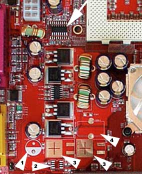
    Close-up of the board power circuitry. The arrow on the top shows where the HIP 6302 controller chip has been spreadeagled to fit the footprint of the much larger 6301 programmable multiphase controller. The arrowheads indicate missing components or more correctly components that were part of the reference design but have been eliminated by the (invisible on a red PCB) red pen (1: cap, 2: driver chip, 3: MOSFETs, 4: choke).
    photo and description courtesy of lostcircuits.com
    Attached Files
  • gg1978
    Badcaps Veteran
    • Dec 2004
    • 431
    • USA

    #2
    Re: 2 Phase to 3 Phase VRM

    That's interesting that they just stuffed 2 of the 3 phases on that board. Have you had a chance to put a scope on the VRM output while the CPU is under heavy stress?? I never thought the Barton core chippies were too demanding on core current, so i would think that 2 phase would be fine, provided there's enough output capacitance to keep Vcore from drooping too much due to the high di/dt's exhibited by all modern CPU's.

    As for feasibility, as long as you're sure that the 6301 is the proper VR controller to go on the PCB, and make sure that the added FET's are a close match to the existing ones. I personally wouldn't bother, provided the system can hold up to at least 72 hours of continuous Prime95 stress testing.

    Comment

    • Oklahoma Wolf
      Badcaps Veteran
      • Dec 2005
      • 353

      #3
      Re: 2 Phase to 3 Phase VRM

      Originally posted by gg1978
      I never thought the Barton core chippies were too demanding on core current, so i would think that 2 phase would be fine, provided there's enough output capacitance to keep Vcore from drooping too much due to the high di/dt's exhibited by all modern CPU's.
      I'm a little unclear on that myself - my AK79G-Max has a 3 phase VRM, yet when I push the Vcore to 1.85v and then push the CPU to 2.4 GHz my software readings go nuts and set off low 5v warnings. Then again, the board does have Lelon and Samsung for caps... can't wait to see how it does with Panasonic FM's all around.

      Comment

      • gg1978
        Badcaps Veteran
        • Dec 2004
        • 431
        • USA

        #4
        Re: 2 Phase to 3 Phase VRM

        I've got a Tyan S2098 (i845GL, 400FSB only, flexATX) board that has a two phase VRM, and i've run a 2.6Ghz/400FSB Northwood on it, with no issues with Vcore. Of course the Tyan board has all panasonic. rubycon, sanyo, and a couple of small Teapo's on it. Not to mention the toroid inductors are a good bit bigger than of the board in Mustang's post.

        Northwood P4 at 2.6Ghz is 1.5V at probably 60A or so, if i had to hazard a guess, without looking at the Northwood datasheet. If i want to really put a Socket A board i'm testing through the wringer, i've got a 1.33Ghz AYHJA Tbird that runs quite happily at 1.5Ghz, 1.8Vcore. I figure if the board can keep the power going to the Tbird, it'll hold up to pretty much any other socket A chip, except in extreme overclocking cases..

        As for your software alarms, the onboard voltage monitoring chip's aren't exactly the most accurate things.. I would recommend checking the +5V with a DMM before assuming you've got that much of a voltage drop. Could be oxidation on your ATX connector too..

        Comment

        • Mustang
          Badcaps Veteran
          • Dec 2003
          • 203

          #5
          Re: 2 Phase to 3 Phase VRM

          There's quite a few MSI designs that skimp on the VRM circuit and just use larger caps to smooth out the power. I also have a newer MSI K7N2G with the same setup(2 phase). It can't even run a mobile at 200 FSB (locks up on boot).
          I don't have a scope so no way to monitor Prime95 in DOS mode that I'm aware of. It probably wouldn't pass anyway.
          The 6301 controller is 3 phase but the board has a 6302 which I'm not sure if it's able to handle 3 phases.
          You're probably right it may just be a waste of time. Maybe just soldering larger caps might help it along enough.
          Last edited by Mustang; 01-19-2006, 09:14 PM.

          Comment

          • gg1978
            Badcaps Veteran
            • Dec 2004
            • 431
            • USA

            #6
            Re: 2 Phase to 3 Phase VRM

            I've got an Abit NF7-S (one of the Abit boards that actually has all GOOD caps on it!!!), and it's 3 phase VRM, powered off the P4 4 pin connector. The mobile Athlon XP's work really well with it, even when overclocked. Of course the NF2/400 chipset was never known for extreme FSB overclocking, so the tweakable multipler on the Mobile XP is quite nice. I wish i would have bought about 2 or 3 more of the NF7-S's when newegg had them on sale.

            Comment

            • Fatal0E
              Badcaps Veteran
              • Jan 2004
              • 252

              #7
              Re: 2 Phase to 3 Phase VRM

              8 Phase power

              http://usa.asus.com/products4.aspx?l...44&modelmenu=1

              Comment

              • Mustang
                Badcaps Veteran
                • Dec 2003
                • 203

                #8
                Re: 2 Phase to 3 Phase VRM

                Originally posted by gg1978
                I've got an Abit NF7-S (one of the Abit boards that actually has all GOOD caps on it!!!), and it's 3 phase VRM, powered off the P4 4 pin connector. The mobile Athlon XP's work really well with it, even when overclocked. Of course the NF2/400 chipset was never known for extreme FSB overclocking, so the tweakable multipler on the Mobile XP is quite nice. I wish i would have bought about 2 or 3 more of the NF7-S's when newegg had them on sale.
                Same setup here, Athlon 2500 mobile on a NF7-S with all Rubycons .It's a great board
                I can't get more than 190 FSB w/o stability issues on my kid's MSI board though. He has the same 2500 mobile as well. You get what you pay for although the NF7-S for $79 at Newegg was a bargain Wish I bought a few more too.

                Comment

                • Oklahoma Wolf
                  Badcaps Veteran
                  • Dec 2005
                  • 353

                  #9
                  Re: 2 Phase to 3 Phase VRM

                  Originally posted by gg1978
                  I would recommend checking the +5V with a DMM before assuming you've got that much of a voltage drop. Could be oxidation on your ATX connector too..
                  I usually do it that way - the board can't even strain my Fortron 530W... still annoys me though watching the software and BIOS readings take that much of a dive when the overclocking starts. Goes from 4.82 all the way down to 4.44 with the PSU measuring a solid 5.09. I think the lowest I ever saw was 4.39.

                  Maybe the board's getting the readings after those Lelon caps... hope the Panasonic FM's help. If I can get them to fit that is (replacing 10mm with 12.5mm). Never really noticed that much fluctuation in Vcore even at 2.4 GHz.

                  Comment

                  • Mustang
                    Badcaps Veteran
                    • Dec 2003
                    • 203

                    #10
                    Re: 2 Phase to 3 Phase VRM

                    Originally posted by Fatal0E
                    Very nice board. If ASUS would add 8 Phase to this board http://usa.asus.com/products4.aspx?l...87&modelmenu=1
                    with an Opteron, it'd be the top enthusiast board on the market today IMHO.

                    Comment

                    • Rainbow
                      Badcaps Legend
                      • Aug 2005
                      • 1372

                      #11
                      Re: 2 Phase to 3 Phase VRM

                      Check the temperature of the mosfets when the CPU is fully loaded. If they don't get very hot and there are no stability problems, I'd leave it as is.
                      See this PCPartner K333ASA-270 board - there are 5 mosfets in the CPU VRM. They're probably arranged as 2 phases somehow. And those 5 caps in a row are 4700uF so a total of 23500uF
                      Attached Files

                      Comment

                      • kc8adu
                        Super Moderator
                        • Nov 2003
                        • 8832
                        • U.S.A!

                        #12
                        Re: 2 Phase to 3 Phase VRM

                        look for a high resistance connection at the atx connector.
                        thats a big drop.measure after the atx.hint.whatever is causing the drop will get hot and will eventually burn.

                        Comment

                        • Per Hansson
                          Super Moderator
                          • Jul 2005
                          • 5895
                          • Sweden

                          #13
                          Re: 2 Phase to 3 Phase VRM

                          Mustang; The only real benefit except cleaner vcore you get from using more MOSFETS is that the load on them naturally decreases so they will not become so damn hot, saving the life of the capacitors around them...

                          I've seen MOSFETS stay at 100°C on some less genious designs by Epox a few years back, loaded with CPU's that of course did not exisist when the boards where originally built...
                          "The one who says it cannot be done should never interrupt the one who is doing it."

                          Comment

                          • Mustang
                            Badcaps Veteran
                            • Dec 2003
                            • 203

                            #14
                            Re: 2 Phase to 3 Phase VRM

                            Originally posted by Per Hansson
                            Mustang; The only real benefit except cleaner vcore you get from using more MOSFETS is that the load on them naturally decreases so they will not become so damn hot, saving the life of the capacitors around them...

                            I've seen MOSFETS stay at 100°C on some less genious designs by Epox a few years back, loaded with CPU's that of course did not exisist when the boards where originally built...
                            That's basically why I'd like to add the 3rd phase. But as Rainbow suggests, I'll check the mosfet temps under load and if ok, will leave as is or pop in some higher rated caps.
                            Last edited by Mustang; 01-20-2006, 03:37 PM.

                            Comment

                            • gg1978
                              Badcaps Veteran
                              • Dec 2004
                              • 431
                              • USA

                              #15
                              Re: 2 Phase to 3 Phase VRM

                              That PC partner board has quite a different layout that most VRM's do. Usually there's a pair of FET's for each phase, one's the top FET, that's connected to the VRM input, and the bottom FET, which goes to ground, with the area in between being the part that goes to the toroid output filter. The top fet pulls the voltage up to the input VRM voltage, while the bottom FET pulls it down. Hence, by varying the duty cycle of the FET's, the output current can change while holding Vcore stable.


                              The reason i say it's weird is that the three FET's right by the ATX connector appear to be "top" FET's but they appear to be connected in parallel, so they'll just work as one big FET, not three individual ones, while the other two appear to be a pair of "bottom" FET's, one per phase, which are right by the two toroid inductors. Hence, it's more like a single phase VRM than a two phase one, just going by looks alone. You'd have to check between the 3 FETs by the ATX connector and verify if they're in parallel to see if that's true or not.

                              I have seen VRM's that have more bottom FET's than top FET's, since the bottom FET's get more of a workout, since Vcore is so low compared to the VRM input voltage, especially with +12V input VRM's being common now.

                              Comment

                              • Rainbow
                                Badcaps Legend
                                • Aug 2005
                                • 1372

                                #16
                                Re: 2 Phase to 3 Phase VRM

                                Originally posted by gg1978
                                The reason i say it's weird is that the three FET's right by the ATX connector appear to be "top" FET's but they appear to be connected in parallel, so they'll just work as one big FET, not three individual ones, while the other two appear to be a pair of "bottom" FET's, one per phase, which are right by the two toroid inductors. Hence, it's more like a single phase VRM than a two phase one, just going by looks alone. You'd have to check between the 3 FETs by the ATX connector and verify if they're in parallel to see if that's true or not.
                                I know that it's weird design - that's why I posted it here.
                                I examined it when I had the board but I forgot it since I only have a more detail scan of the board, hopefully enough to read the marking on the VRM controller chip.

                                Comment

                                • Mustang
                                  Badcaps Veteran
                                  • Dec 2003
                                  • 203

                                  #17
                                  Re: 2 Phase to 3 Phase VRM

                                  Found out a few things. The Intersil HIP 6302 is a dual phase controller..so much for adding caps and a choke.
                                  3 caps by the VRM are 1500uf while the other 5 by the cpu are 2200uf. My fried ASUS A7N8X board is also dual phase but has 8 3300uf caps. Maybe go with that value.
                                  Running Prime95 so far no problems. Mosfets are just warm to touch but I did put heatsinks on them.

                                  Comment

                                  • gg1978
                                    Badcaps Veteran
                                    • Dec 2004
                                    • 431
                                    • USA

                                    #18
                                    Re: 2 Phase to 3 Phase VRM

                                    Originally posted by Mustang
                                    Found out a few things. The Intersil HIP 6302 is a dual phase controller..so much for adding caps and a choke.
                                    3 caps by the VRM are 1500uf while the other 5 by the cpu are 2200uf. My fried ASUS A7N8X board is also dual phase but has 8 3300uf caps. Maybe go with that value.
                                    Running Prime95 so far no problems. Mosfets are just warm to touch but I did put heatsinks on them.

                                    THat's why the spot the 6302 is soldered to has some extra pads close by. The three channel PWM controller most likely has more pins, for the control of one or two more phases. I have seen some VRM controllers that support up to 4 phases, but they can be configured to operate less. I've got an Epox board i've been contemplating recapping for a while..

                                    Comment

                                    • Mustang
                                      Badcaps Veteran
                                      • Dec 2003
                                      • 203

                                      #19
                                      Re: 2 Phase to 3 Phase VRM

                                      The board ran 20 hours of Prime95 without an error. The wife needed to do a bit of shopping ...so that cut testing short.

                                      Considering it's intended usage, It's probably stable enough. Thanks for all the tips and ideas

                                      Comment

                                      • Per Hansson
                                        Super Moderator
                                        • Jul 2005
                                        • 5895
                                        • Sweden

                                        #20
                                        Re: 2 Phase to 3 Phase VRM

                                        Originally posted by Per Hansson
                                        I've seen MOSFETS stay at 100°C on some less genious designs by Epox a few years back, loaded with CPU's that of course did not exisist when the boards where originally built...
                                        Just for kicks I wanted to see how much power I could get my comp to draw.

                                        As a side effect of this the temp of my MOSFETS increased slightly, when I ran the system at 1.60v 2.3ghz they never went above 70°C. So I increased the vcore to 1.80v and CPU speed to 2.5ghz, the MOSFET temp recorded by the thermsistor I placed in between two of the 6 MOSFETS was 93°C! So it's a good thing Epox choose to use only high quality GSC caps for the 12v input and TEAPO for the output caps and then place the caps so far away from the MOSFETS... Mind you the VRM design on this board is 3 phase, Many of AMD's processors require 1.75v vcore so my little test is really not that unnatural... So if I where you I would keep a close eye on the temp of that 2 phase VRM design Mustang!
                                        Attached Files
                                        Last edited by Per Hansson; 04-16-2016, 05:50 AM. Reason: Offsite image uploaded due to problems with host
                                        "The one who says it cannot be done should never interrupt the one who is doing it."

                                        Comment

                                        Related Topics

                                        Collapse

                                        • Document Archive
                                          HP Compaq Elite 8200 Compaq Elite 8200 i5-2500 Specification for Upgrade or Repair
                                          by Document Archive
                                          This specification for the HP Compaq Elite 8200 can be useful for upgrading or repairing a desktop PC that is not working. As a community we are working through our specifications to add valuable data like the Compaq Elite 8200 boardview and Compaq Elite 8200 schematic. Our users have donated over 1 million documents which are being added to the site. This page will be updated soon with additional information. Alternatively you can request additional help from our users directly on the relevant badcaps forum. Please note that we offer no warranties that any specification, datasheet, or download...
                                          09-12-2024, 03:36 PM
                                        • SavaBogdan
                                          Help disabling a vcore phase on a MSI X570 Carbon - I have schematics + boardview
                                          by SavaBogdan
                                          Hello.
                                          Does anyone have any experience with disabling a power phase on the CPU vrm?
                                          The controller is IR35201 6+2 phases. It only uses 5 phases and the pins for pwm and feedback on the 6'th phase are not populated (no traces).
                                          I got the board with a burned mosfet which I removed along with a part of the pcb. I dremelled away the short as best I could and the board started up fine without the vrm heatsink.
                                          I then put some sealant and left it for two days to completely dry. I suspect the pressure from the thermal pads on the heatsink compressed the layers so when I started...
                                          10-21-2022, 10:05 AM
                                        • Axis937
                                          BQ 727 Chip 2.4V at Phase
                                          by Axis937
                                          HI folks 1 question on ablout BQ 727 IC. I believe that it is also meant to charge the battery based on the proximity to the battery pins. I have a strong feeling that the battery is dead but i will look at it later. My question is VCC on BQ is receiving the ADP voltage of 19V. However PHASE and HiDRV on BQ is only pushing out about 2.4V with or without battery attached. That 2.4 V is heading to the gate of the charging mosfet. Source is also pushing out the same 2.4V. Finally the battery voltage pin is receiving 2.2V. Do you see this as a issue or no issue. Battery is likely faulty as well as...
                                          09-24-2024, 08:49 AM
                                        • aysat
                                          MSI GTX 970 Golden Edition phase restore problem
                                          by aysat
                                          Hi everyone,

                                          I have the weirdest problem of a core phase restoring. I have replaced the doubler, driver and the drmos and checked all the resistors around the main inductor but still there is no switching on that phase. I even swapped these phase with another but still no go. I checked around the voltage regulator ncp81174 but could not find a culprit. i have board scheme but that did not help either. got oscillator and everything but it drives me crazy.

                                          Has anyone observed such a behavior before ? I am out of ideas. any help would be appreciated. i will post some...
                                          03-03-2023, 01:09 AM
                                        • vincentedel
                                          Samsung SyncMaster 740n Phase Control Issue
                                          by vincentedel
                                          Hello,
                                          I'm having an issue with the Samsung 740n's phase control setting. When I use the automatic adjustment, it sets the value to around 54 (with a range of 0-100), and the picture looks clear and sharp. However, after some time—like after playing a game—the text starts to look blurry. When I auto-adjust again, it may increase the value to 80, and everything becomes sharp once more. Yet, after a while, whether it's a few hours or a day later, the same blurriness returns, and I have to adjust it again.

                                          I'm using the Samsung 740n monitor drivers instead of the default plug-and-play...
                                          04-22-2025, 12:33 AM
                                        • Loading...
                                        • No more items.
                                        Working...