
Hi all,
Ive set this post up from a previous one.
This way i can make it eaisier to explain properly, and slowly work through the troubleshooting process on motherboards.
The Problem
I was using A Pentium 4 Prescott 2.8Ghz skt478 in a Shuttle XPC: FB61R v2.1, not realising it didnt support this cpu and that it would damge it.
It worked flawlessly for a year, and then realising that i should be using northwood based cores (the MOSFETS wre roastingly hot), I purchased a 2.6Ghz Northwood and installed it only to find the board wouldnt boot.
The lights and fans were on but nobody was home.
I worked thru all the usual troubleshooting routines, but i just could not get the northwood to boot (its working fine in my currnet DFI board).
So, i gave up and returned to using the prescott/shuttle again, However i did find a BIOS update, but it didnt give prescott support (research has revealed that BIOS updates alone will not give compatibilty, FMB 1.5 will).
This BIOS flash didnt work, and the system then refused to boot with either CPU installed.
This was getting frustrating.
I resorted to hotflashing the shuttles SST chip in my DFI, as they are the same model of eeprom.
The Hotflash went fine using UniFlash BUT.........
CARELESSLY, i put the chip in the shuttle socket the wrong way.
You may aks how i did this, as the EEPROM socket are keyed in the corner.
Well, i cracked the plastic socket when i removed the EEPROM, and being in an awkward place, and being to careless, i replaced the newly flashed EEPROM in right side up, wrong way round :-(
This was almost instantly realised, wehn i booted up, nothing happened, and i ran my finger over the EEPROM....it was boiling hot!.............oops
So, i ordered a nwly flashed SST EEPROM chip, installed and now im back to where i was.......the lights and fans are on but nobody is home.
What ive tested
The EEPROM (SST 49LF004B 3.3v) and socket has been tested, the VDD for the chip on pin #32 = 3.35v
This was measured against Pin #16, the VSS ground and atx ground.
This looks good as its a 3.0 -3.6v chip.
Components:
CPU = Tested, Working
RAM = Tested, Working
GFX = Tested, Working
HDD = Tested, Working
PSU = Tested, Working
What next?
So now im down to the motherboard,
I understand that the MOSFET's and/or Capacitors could be blown/faulty and this is where i need some help.
What method should i next use for the process of elimination?
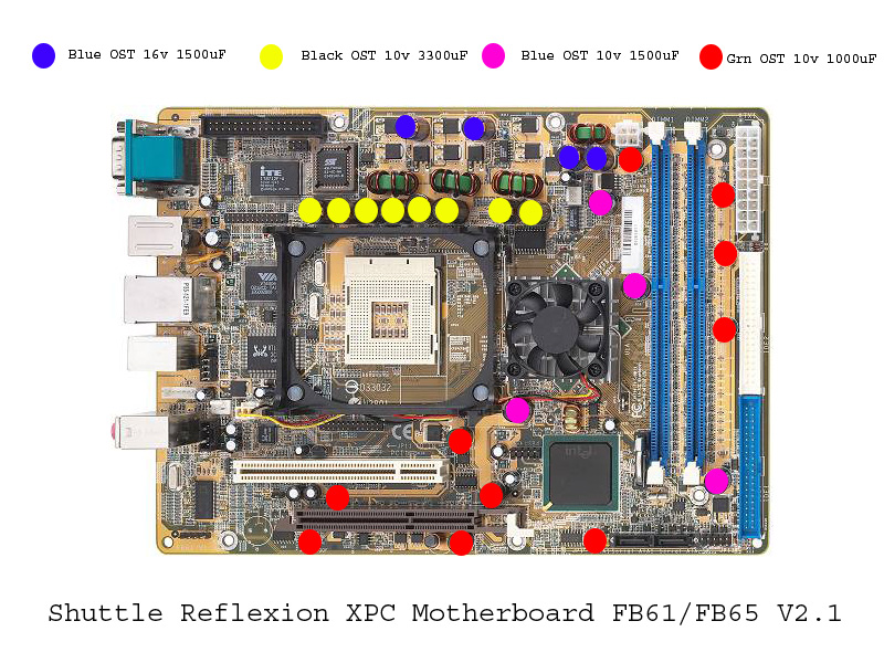
Heres the board in question:
If you can help me out on this process of elimination, that would be superb and greatly appreciated.
If possible, please try not to stray too much off topic, id like to keep it specific, with suggestions and results posted only.
Thanks in advance
Ive set this post up from a previous one.
This way i can make it eaisier to explain properly, and slowly work through the troubleshooting process on motherboards.
The Problem
I was using A Pentium 4 Prescott 2.8Ghz skt478 in a Shuttle XPC: FB61R v2.1, not realising it didnt support this cpu and that it would damge it.
It worked flawlessly for a year, and then realising that i should be using northwood based cores (the MOSFETS wre roastingly hot), I purchased a 2.6Ghz Northwood and installed it only to find the board wouldnt boot.
The lights and fans were on but nobody was home.
I worked thru all the usual troubleshooting routines, but i just could not get the northwood to boot (its working fine in my currnet DFI board).
So, i gave up and returned to using the prescott/shuttle again, However i did find a BIOS update, but it didnt give prescott support (research has revealed that BIOS updates alone will not give compatibilty, FMB 1.5 will).
This BIOS flash didnt work, and the system then refused to boot with either CPU installed.
This was getting frustrating.
I resorted to hotflashing the shuttles SST chip in my DFI, as they are the same model of eeprom.
The Hotflash went fine using UniFlash BUT.........
CARELESSLY, i put the chip in the shuttle socket the wrong way.
You may aks how i did this, as the EEPROM socket are keyed in the corner.
Well, i cracked the plastic socket when i removed the EEPROM, and being in an awkward place, and being to careless, i replaced the newly flashed EEPROM in right side up, wrong way round :-(
This was almost instantly realised, wehn i booted up, nothing happened, and i ran my finger over the EEPROM....it was boiling hot!.............oops
So, i ordered a nwly flashed SST EEPROM chip, installed and now im back to where i was.......the lights and fans are on but nobody is home.
What ive tested
The EEPROM (SST 49LF004B 3.3v) and socket has been tested, the VDD for the chip on pin #32 = 3.35v
This was measured against Pin #16, the VSS ground and atx ground.
This looks good as its a 3.0 -3.6v chip.
Components:
CPU = Tested, Working
RAM = Tested, Working
GFX = Tested, Working
HDD = Tested, Working
PSU = Tested, Working
- PSU has been tested with multimeter, the numbers look good from the PSU side, all rails are displaying correctly.
What next?
So now im down to the motherboard,
I understand that the MOSFET's and/or Capacitors could be blown/faulty and this is where i need some help.
What method should i next use for the process of elimination?
Heres the board in question:
If you can help me out on this process of elimination, that would be superb and greatly appreciated.
If possible, please try not to stray too much off topic, id like to keep it specific, with suggestions and results posted only.
Thanks in advance
Attached Files
if you find these attachements useful please consider making a small donation to the site


Comment