Thank you to the guys at HEGE supporting Badcaps [ HEGE ] [ HEGE DEX Chart ]

Announcement

Collapse
No announcement yet.

ASUS X99-A, usual 00 code, ME voltage 1.4 instead of 1.05 ...

Collapse
X
 
  • Filter
  • Time
  • Show
Clear All
new posts

    ASUS X99-A, usual 00 code, ME voltage 1.4 instead of 1.05 ...

    As the title say, this is pretty common proble with x99 board.
    Since the 1.05 ME voltage was too high, I suspect PCH is damaged ... but anyway, I want to give it a try bypassing the PS chip .... the idea came up
    reading this post on a chinese bbs ...

    https://bbs.pigoo.com/forum.php?mod=...591&pid=949894

    This one is RT8065ZQW,
    One piece of Taobao is converted into NT$15,
    The open-air just checked is 45 yuan, you can buy it at your own discretion,

    Another way is to change the circuit, remove the RT8065,
    "+1.5_PCH (bridge power supply)" flying lead to "+1.5ME (ME power supply)",
    At the same time, connect the "S_APWORK" flying wire of the 8th pin of RT8065 to "P_OPWORK_10",
    However, I can't find the ASUS X99-WS/SYS bitmap on the Internet.
    I can't tell you a clear way to change it,

    Maybe buy RT8065ZQW directly to change, the easiest,
    This one is very easy to break, how long did you use it last time, and the lifespan next time will be almost that long,
    If you know Taobao, you can buy a few more,
    In addition, this one is WDFN3x3-8 package, it is a bit difficult to solder with air gun,
    If you are not proficient, it is best to google youtube teaching first,
    Or ask a master OEM,
    I think he is right .... but I already try and the board, this time, shut off immediately (voltages here is 1.05 not 1.5 .... he probably got confused).

    Note:In case you ask yourself if I checked the FB voltage divider of the chip .... yes, I did and everything was fine ... so I blamed the chip itself.

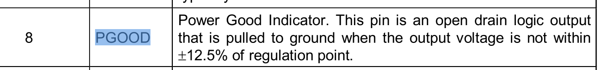
    So, I removed the richtek chip powering ME subsection of the chipset ... I then connected PCH 1.05 to ME 1.05 (after the inductor) ..... but the problem is the power ok signals. He said to connect the APWROK to OPWORK_10 ... but I checked the schematics and the last one doesn't connect to the chip.


    The components involved are not there (and this is right, the schematics don't indicated any component there) and the specific signal is not present in any other part of the board.

    So I guess he got this part wrong. APWROK is connect to the chip, so it has to be assert for the chip to accept the voltage supply for ME .... but how?

    #2
    Re: ASUS X99-A, usual 00 code, ME voltage 1.4 instead of 1.05 ...

    APWROK, alias PGOOD of the richtek chip, is pulled up by a resistor to 3,3v.

    Is an open drain pin ...


    and the internal mosfet pull down the voltage to ground if it's not in the range.

    Comment


      #3
      Re: ASUS X99-A, usual 00 code, ME voltage 1.4 instead of 1.05 ...

      Had a lot motherboard on X99 that had a problems with ME voltage at range 0.6-1.6v (on my opinion RT8065 is a bad solution) only replacement of chipset can you help. That all.

      Comment


        #4
        Re: ASUS X99-A, usual 00 code, ME voltage 1.4 instead of 1.05 ...

        Originally posted by cobovo View Post
        Had a lot motherboard on X99 that had a problems with ME voltage at range 0.6-1.6v (on my opinion RT8065 is a bad solution) only replacement of chipset can you help. That all.
        I agree, but before giving up on chipset, I want to try this bypass so
        I can be sure it's dead.

        I don't think it's a bas idea ... it's easy to put 1.05 on ME from PCH ...
        it's right there ... you have only to connect together the output of the two inductors (pl500 e pl502). But what about apwrok? It's needed, otherwise the
        board shut down immediately.


        Do you have any experience with the pgood signal architeture for x99?
        APWROK is directely connected to the chipset ... but I wonder if it also directely involved in enable other voltages needed.

        Why did he think to connect apwrok and p_opwrok_10???

        Comment


          #5
          Re: ASUS X99-A, usual 00 code, ME voltage 1.4 instead of 1.05 ...

          this is the schematic ...
          Attached Files

          Comment


            #6
            Re: ASUS X99-A, usual 00 code, ME voltage 1.4 instead of 1.05 ...


            SLP_A# is the signal coming from the chipset enabling the richtek chip .... then
            he generates the 1.05me voltage and give the pgood/apwrok signal back to the chipset.

            So I don't understand why he was taking about p_opwrok_10

            Comment


              #7
              Re: ASUS X99-A, usual 00 code, ME voltage 1.4 instead of 1.05 ...

              I tried this mod with no luck .... so, or the chipset is dead
              or it's not quick enough. This because apwrok can be assert before but not after pwrok ...

              anyway I can't think of anything different.

              In standby VSB put APWROK to 0v .... if SLP_A# rise, the second
              mosfet shutdown the first and APWORK rise up to 3,3v

              It's more or less what richtek chip does.
              Attached Files

              Comment


                #8
                Re: ASUS X99-A, usual 00 code, ME voltage 1.4 instead of 1.05 ...

                Be sure, HUB is Dead. Because the ME region in HUB is important part of Intel ECO systems and you can't bypass him in any ways, never!

                Comment


                  #9
                  Re: ASUS X99-A, usual 00 code, ME voltage 1.4 instead of 1.05 ...

                  Important note: Always replace RT8065 with the HUB. First replace RT8065 then check a voltage and only after that you able to replace the HUB!!!!

                  Comment


                    #10
                    Re: ASUS X99-A, usual 00 code, ME voltage 1.4 instead of 1.05 ...

                    Originally posted by cobovo View Post
                    Be sure, HUB is Dead. Because the ME region in HUB is important part of Intel ECO systems and you can't bypass him in any ways, never!
                    Anyway I was trying to bypass the richtek PSU, not ME ... what I tried
                    was to power ME up with the core 1.05 voltage and give the pgood signal
                    in another way. Andthe circuit I made actually work fine, but the chipset is dead.

                    Comment


                      #11
                      Re: ASUS X99-A, usual 00 code, ME voltage 1.4 instead of 1.05 ...

                      hello people , well.... another, in here in the same isue, 1.65v in pch arghhh kill the pch my board x99 deluxe/u3.1.


                      thanks guys, i did direct to check voltage.

                      systems start, q-code run for 9 number, last one is 30 them 00 and shuts down. pch hot.

                      now thinking if i will get the trouble to buy a new one and replace ( 40€)
                      Attached Files

                      Comment


                        #12
                        Originally posted by cobovo View Post
                        Re: ASUS X99-A, usual 00 code, ME voltage 1.4 instead of 1.05 ...

                        Important note: Always replace RT8065 with the HUB. First replace RT8065 then check a voltage and only after that you able to replace the HUB!!!!
                        I bought an Asus X99 USB 3.1 mobo for a project and turned out to have this specific issue (not posting and giving 00 code), only way to make it post was to clear cmos and then it was very random when it started rebooting or just not posting with code 00

                        I have quite a lot of experience in electronics repair but not into the world of MOBO's.

                        Indeed each time the mobo was able to post the ME voltage was in the expected value, and each time it was giving code 00 it was around 0.9V. I know that there are other users that have it with bigger voltages (up to ~1.6V)

                        From an electronics perspective the dc-dc converter should be able to regulate the output and failing to do it is either.

                        1. Defective resistors values which make the feedback wrong
                        2. Too much load and then the regulator can't regulate anymore
                        3. Strange voltage input at the dc-dc converter.

                        So I could deduce that if you are experiencing a lower ME voltage it could be due to a high load connected to the output (which was not my case) and easily to find as the IC will get quite hot if this is the case

                        For users that are with a higher ME voltage (which is worse than lower as then the HUB can be compromised due to the elevated voltage) it could mean that there isn't enough load connected to the output of the DC-dc converters but I don't find anything related to this in the datasheet and on my experience I would find it strange that is not able to regulate.

                        In my case the output was at 0.9V and the feedback voltage (0.8V) was also OK. Input voltage looked fine. Although you suggested that the HUB was the issue I think about it as terms of load and in my specific case it didn't make sense that the issue was the HUB (also cuz I was able to post after clearing CMOS, that I think it works as it bypasses some kind of check of that specific voltage or some timing is less strict?... don't have enough experience to know why this works)..... I also checked the resistors without the DC-dc converter connected and they looked OK and with the expected value.

                        Decided to replace the RT8065 and then the mobo started posting consistently. Previous things that made it fail are now working OK.

                        In case you are experiencing some of the same symptoms you might want to check the ME voltage and in case you find something abnormal try to replace it. (In my case it was a faulty internal issue with the RT8065 )

                        - Check the ME voltage and in case is out of specs do:

                        1. Check the input voltage of the RT8065
                        2. Check the feedback voltage.
                        3. Remove it and measure the feedback resistances (with the RT8065 on circuit I had very strange readings of the resistance) in case of doubt remove the resistors and measure them out of circuit.
                        4. Re test.

                        This is all to say that is worth the shot at replacing it as I think there is definetly something internal making it fail.


                        Ofc in case is the HUB I think is economically not very attractive to repair it unless you have access to cheap parts.

                        What I know is that the dc-dc converter should give the correct output if the feedback is at 0.8 and the ratio of the resistors is OK. And this has nothing to do with what you connect at the output (unless ofc you are draining a lot more of what the regulator can do)

                        Hope this helps someone

                        Comment

                        Working...
                        X