Pioneer VXS-D902S Reciever - Filter Capacitor Question

Collapse
X
 
  • Time
  • Show
Clear All
new posts
  • grimacelord
    Badcaps Veteran
    • Jan 2017
    • 380
    • USA

    #1

    Pioneer VXS-D902S Reciever - Filter Capacitor Question

    Hello,

    I have a Pioneer VSX-D902S receiver that I am trying to replace the 2 large 8200uF 80V filter capacitors on.

    I have already removed the capacitors and ordered replacements, but I made a mistake in ordering. The original capacitors are Pioneer ACH1202 80v 8200uF and have 4 pins. The capacitor replacements I bought are Nichicon 80v 8200uF and only have 2 pins.

    I was wondering if I could still use my replacements even though they only have 2 pins. Obviously I'd have to extend the pins of the capacitor to allow them to reach and fit through the holes in the PCB, but I just wanted to make sure that it would be safe to do so judging by the additional information I have below.

    Here is a side-by-side image of the original capacitor and my replacement. The original is on the left and my replacement is on the right.


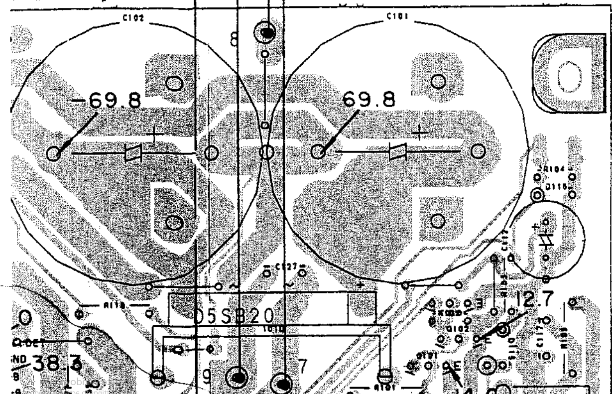
    Here is the relevant section of the service manual (found on page 54, although the image is mirrored in the manual. Need to use an image editing program to flip the image so it's readable) for these two caps:


    And here is an image of the board with both caps removed:


    And here is the full service manual:
  • Per Hansson
    Super Moderator
    • Jul 2005
    • 5895
    • Sweden

    #2
    Re: Pioneer VXS-D902S Reciever - Filter Capacitor Question

    Sure, but a more professional look and also secure mounting would be had by drilling new holes so the new caps actually fit
    "The one who says it cannot be done should never interrupt the one who is doing it."

    Comment

    • grimacelord
      Badcaps Veteran
      • Jan 2017
      • 380
      • USA

      #3
      Re: Pioneer VXS-D902S Reciever - Filter Capacitor Question

      Originally posted by Per Hansson
      Sure, but a more professional look and also secure mounting would be had by drilling new holes so the new caps actually fit
      Hi there.

      Thanks for the suggestion of drilling new holes. I'm not sure I feel comfortable doing that because for one, I've never done that before and two, how do I know that I'm not drilling through some traces for various circuits that might be within the layers of the PCB?

      My idea was to cut off some capacitor pins from a new electrolytic cap and solder those on to the pins of my 80v filter caps to extend them and then bend them in a way where they reach the existing holes in the board and solder them in place as usual. Then to secure the caps so they don't move much, I was trying to decide between using a lot of UV solder mask, an adhesive such as B6000, or regular silicone caulking one might use in their kitchen or bathroom. Although it might not necessarily have the best visual appearance, the main goal here is functionality and safety. I just wanted to get some opinions on whether it would work and if it would be safe.

      It looks to me (according to my interpretation of the schematic), that the two extra pins on the original capacitors aren't connected to anything at all. They are just purely for stabilizing the large caps so they won't wobble around. I did check those pins on the board to see if they were connected to ground and they were not. I checked to see if they were connected to the anode side of the cap and they were not. The schematic doesn't appear to show them being connected to anything else, so would I be right in my assumption that they are just "anchor points" to stabilize the large caps?

      Thank you for your help.

      Comment

      • Per Hansson
        Super Moderator
        • Jul 2005
        • 5895
        • Sweden

        #4
        Re: Pioneer VXS-D902S Reciever - Filter Capacitor Question

        Originally posted by grimacelord
        Thanks for the suggestion of drilling new holes. I'm not sure I feel comfortable doing that because for one, I've never done that before and two, how do I know that I'm not drilling through some traces for various circuits that might be within the layers of the PCB?
        Old stereo stuff is simple, always single layer so there is no problem to drill it, you can always confirm it with a strong flashlight from behind the board...
        Originally posted by grimacelord
        It looks to me (according to my interpretation of the schematic), that the two extra pins on the original capacitors aren't connected to anything at all. They are just purely for stabilizing the large caps so they won't wobble around. I did check those pins on the board to see if they were connected to ground and they were not. I checked to see if they were connected to the anode side of the cap and they were not. The schematic doesn't appear to show them being connected to anything else, so would I be right in my assumption that they are just "anchor points" to stabilize the large caps?
        Yes this is correct and it is the reason why I suggest to drill new holes: it will be hard to make a stable (vibration proof) mount of the new capacitors in any other way.
        People do otherwise make adapter PCB's to mount capacitors, I linked such a thread below.
        Do read it and check if the idea redwire came up with in post #11 can be used here, i.e. does the new cap reach any two holes in the PCB?
        https://www.badcaps.net/forum/showth...656#post845656
        "The one who says it cannot be done should never interrupt the one who is doing it."

        Comment

        • grimacelord
          Badcaps Veteran
          • Jan 2017
          • 380
          • USA

          #5
          Re: Pioneer VXS-D902S Reciever - Filter Capacitor Question

          Originally posted by Per Hansson
          Do read it and check if the idea redwire came up with in post #11 can be used here, i.e. does the new cap reach any two holes in the PCB?
          https://www.badcaps.net/forum/showth...656#post845656
          Thanks for the link! I was able to use redwire's idea of running a jumper diagonally to the "mounting" holes from the anode/cathode. After soldering everything in place, it seemed pretty stable, but I still used some silicone "gasket maker" sealant around the base of the capacitors. In 24 hours, it will harden similar to the white sealant they use at the base of the capacitors from the factory. I figure between redwire's idea and the liberal use of the sealant, that should keep things nice and stable.

          Just finished testing everything and everything seems to be good now! Thanks for the help!

          Comment

          • Per Hansson
            Super Moderator
            • Jul 2005
            • 5895
            • Sweden

            #6
            Re: Pioneer VXS-D902S Reciever - Filter Capacitor Question

            Glad to hear it! If you took any photos of the finished thing do please post them
            "The one who says it cannot be done should never interrupt the one who is doing it."

            Comment

            Related Topics

            Collapse

            • corrize
              Where to find a very small fpc connector 0.3mm between 2 pins ?
              by corrize
              Hello, I search this connector (oxydated).
              It's a fpc zif low profile connector. It come from camera sensor, it is very small : 0.3mm between 2 pins.
              I ordered 2 from Aliexpress called « 0.3mm pitch » but one was 0.5mm between 2 pins and the other 0.6mm. In fact « 0.3mm pitch » seams to be the pad width and not the distance between 2 pins.
              I can't find it. The other websites like mouser dont show the datasheet, and I can't check if it is 0.3mm between 2 pins ?


              Do you know how to find this connector please ? What is the exact name for find it ?

              ​...
              08-06-2024, 05:25 PM
            • madan1
              Modding HPF filter
              by madan1
              Hi everyone.
              Recently scored a dead amp from a mackie srm1801 subwoofer and after fixing it, now I'm thinking about a home cinema/party subwoofer project.
              Most likely I will use a 15" JBL woofer, which I already have and a diy box.

              After reading the mackie user manual, I noticed that it has a 40hz HPF (labeled as "36Hz BUTTERWORTH HPF" in the SM) to protect the speaker from low frequencies. Indeed this seems to be good idea for the intended usage - professional music subwoofer, but bad for movies, where one would expect to "feel" the SUBwoofer....
              09-24-2025, 02:06 PM
            • Bushcat
              Pioneer PL-X9 motor speed control wobble
              by Bushcat
              I'm starting to re-cap a Pioneer PL-X9 turntable, specifically the motor control board, because although everything tests out OK according to the service manual, the speed wavers slightly despite the quartz lock light remaining on. So, I've decided to re-cap that board since it's the cheapest next step...

              Pioneer's passive component naming convention is clear to me. For example, CSZA R22M 35 is tantalum, radial leads, 0.22uF, 20%, 35V.

              BUT there are two capacitors on the board which have actual Pioneer part numbers: PCL-042. I can tell they are 0.1uF, 16V but don't...
              05-24-2023, 03:36 AM
            • SS454
              vizio e650i-a2 backlight flashes then turns off
              by SS454
              vizio e650i-a2 (LWJAOZBP Serial) led backlight flashes then turns off, has video (via flashlight) and audio.

              panel: au optronics T650HVN05.4
              72 led total on 12 strips, 6 led per strip wired in three groups of 24 (led driver board has three anode and three cathode pins)
              link to datasheet: https://datasheetspdf.com/pdf-file/8.../T650HVN05.4/1

              Vizio 56.04219.641G (liteon PA-3231-01WN-LF) Power Supply Unit
              https://www.shopjimmy.com/vizio-56-0...-power-supply/

              Vizio 55.75J01.001G (91.75J10.004G) Main Board...
              08-20-2020, 03:57 PM
            • Agent24
              Dick Smith Q-1760 linear power supply filter capacitor question
              by Agent24
              I have acquired a used Dick Smith Q-1760 power supply - although the OEM is Manson Industrial
              It has at least one problem.

              The voltage control potentiometer VR2, 50K is faulty - going high resistance / open circuit in the CCW end and leading to the output voltage jumping around.
              I have already ordered a replacement potentiometer, so that's not an issue.

              Now, I want to replace all three electrolytics on the PCB as they are CapXon and I don't trust them so much, I will replace them with something better while I've got the thing apart anyway.
              All are CapXon...
              10-21-2025, 05:39 PM
            • Loading...
            • No more items.
            Working...