T.RSC8.10B 12305 ADJ voltage level for RLED4010A

Collapse
X
 
  • Time
  • Show
Clear All
new posts
  • paulstef
    Badcaps Veteran
    • Dec 2013
    • 724
    • Canada

    #1

    T.RSC8.10B 12305 ADJ voltage level for RLED4010A

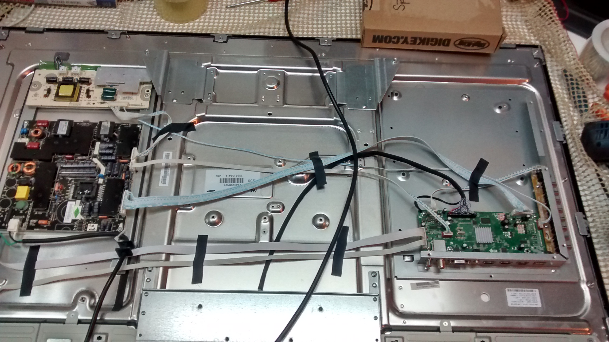
    I made someone buy the mainboard because it has like many other similar boards an intermittent fault, sometimes you could turn the TV on and sometimes not. When you can't there is 0.05V on the ON/OFF signal towards the inverter.

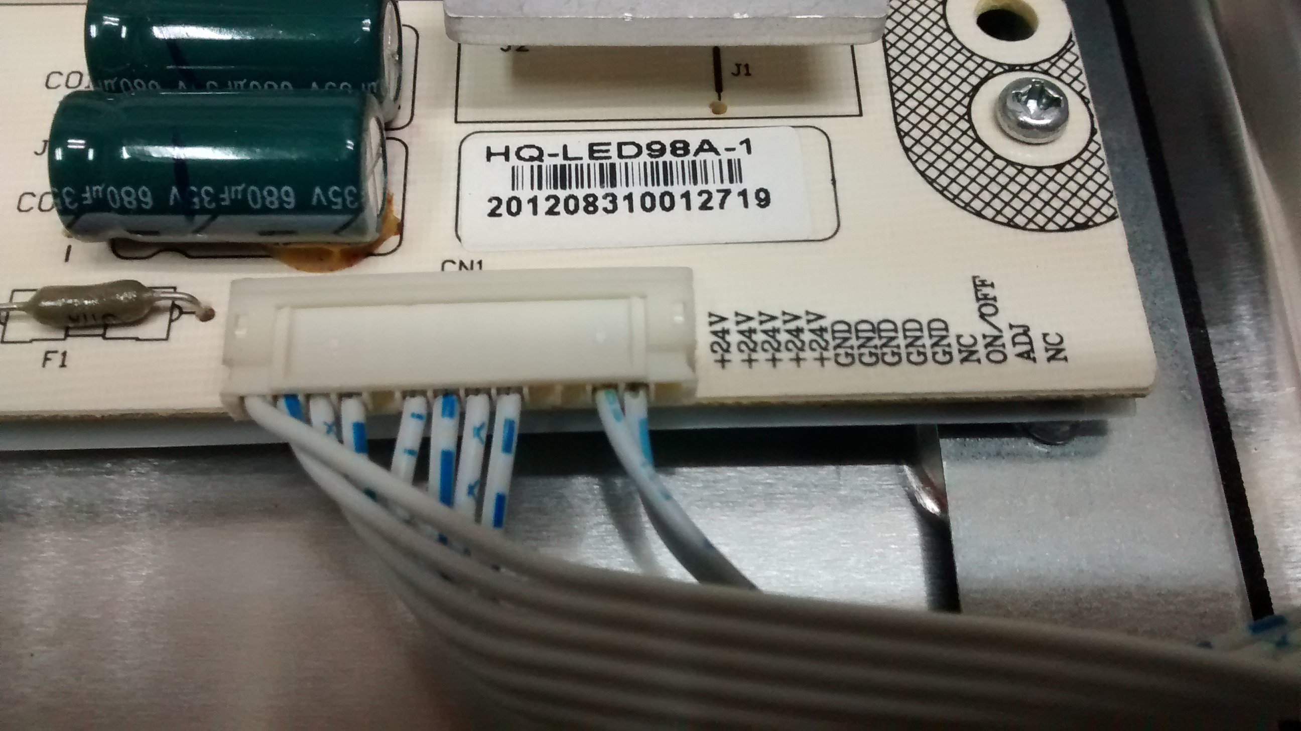
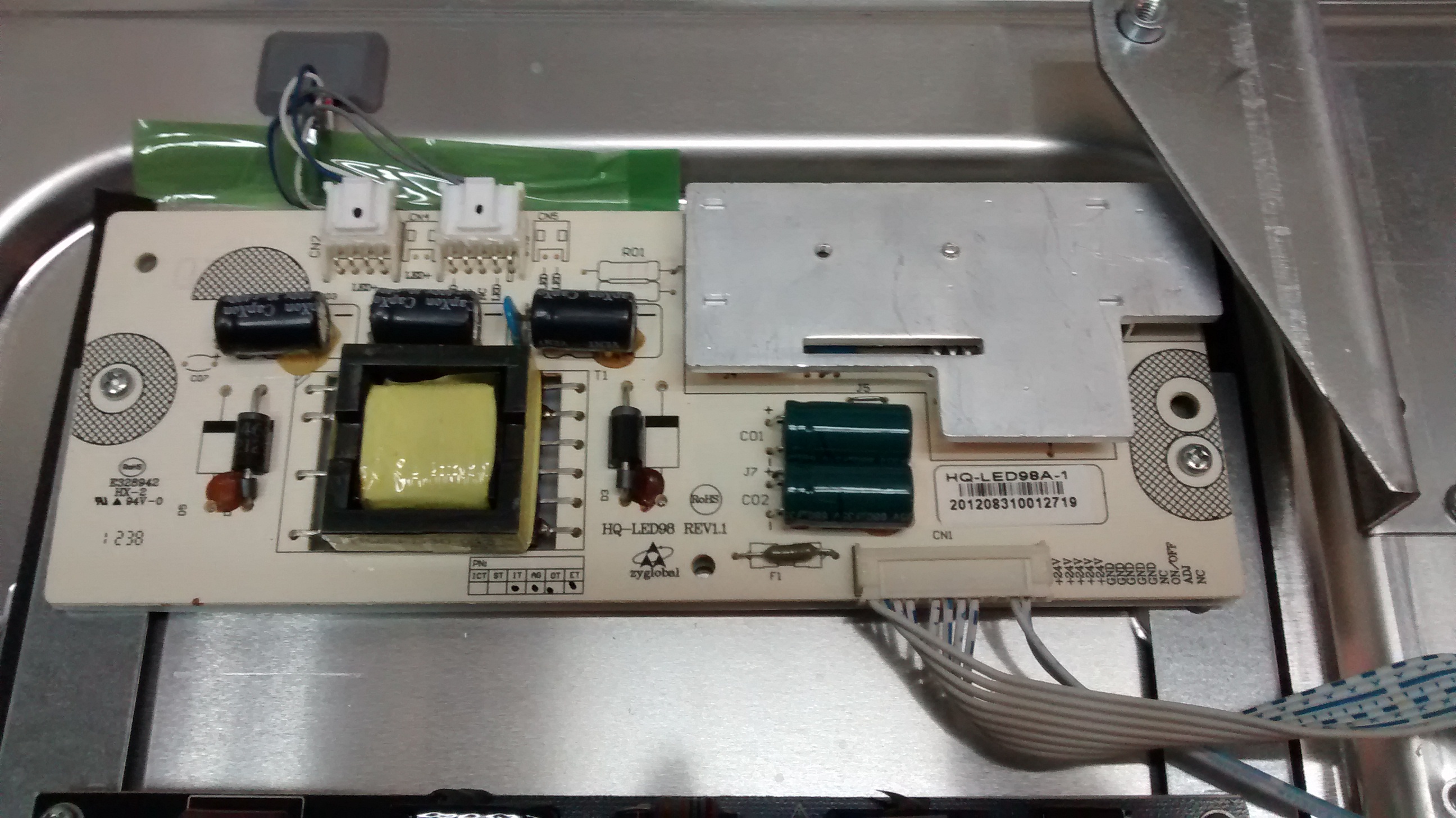
    Now with the new board there is 24V on the inverter, Fuse is ok, 5V on ON/OFF and 5V on ADJ. There is 24V on the LED connector and no backlight.
    The TV is responsive to the standby button which it wasn't before, so the mainboard seems to be ok so far, at least regarding the ON/OFF signal issue.

    My question is: Is ADJ usually a PWM or is it a DC voltage of varying level?
    Can I make things worse by applying a varying DC level directly to the ADJ pin?

    Thanks


    Attached Files
  • paulstef
    Badcaps Veteran
    • Dec 2013
    • 724
    • Canada

    #2
    Re: T.RSC8.10B 12305 ADJ voltage level for RLED4010A

    To answer my own question: It seems to be pure DC.

    With the old board after many many trials I got it running. ON/OFF is 5V and ADJ is 0.98V when running.

    I wonder if there is an adjustment to be made in the new board to change the value of ADJ or if it's just faulty too. Not lucky.

    Comment

    • budm
      Badcaps Legend
      • Feb 2010
      • 40746
      • USA

      #3
      Re: T.RSC8.10B 12305 ADJ voltage level for RLED4010A

      If it is DC 0~5 analog, then it should vary up and down, if it is PWM (10% (min brightness) ~ 90%(max brightness) at around 200~300 Hz), you disconnect the wire, it will be full brightness if there is pull up resistor.
      Never stop learning
      Basic LCD TV and Monitor troubleshooting guides.
      http://www.badcaps.net/forum/showthr...956#post305956

      Voltage Regulator (LDO) testing:
      http://www.badcaps.net/forum/showthr...999#post300999

      Inverter testing using old CFL:
      http://www.badcaps.net/forum/showthr...er+testing+cfl

      Tear down pictures : Hit the ">" Show Albums and stories" on the left side
      http://s807.photobucket.com/user/budm/library/

      TV Factory reset codes listing:
      http://www.badcaps.net/forum/showthread.php?t=24809

      Comment

      • paulstef
        Badcaps Veteran
        • Dec 2013
        • 724
        • Canada

        #4
        Re: T.RSC8.10B 12305 ADJ voltage level for RLED4010A

        Got the backlight working by putting 2.5V on ADJ.

        Only problem: The image is upside down!!! It shows Proscan instead of RCA at the beginning so it's a programming issue.

        I wonder if it's in an external eeprom OR in a OTP in the uC... There is a heatsink on the uC so I can't see what it is... Maybe it's programmable via a service menu?

        Comment

        • paulstef
          Badcaps Veteran
          • Dec 2013
          • 724
          • Canada

          #5
          Re: T.RSC8.10B 12305 ADJ voltage level for RLED4010A

          Swapping the memory chip U16 does it. TV works.

          Which means you can buy ANY T.RSC8.10B 12305 board, swap U16 and it will probably work.

          Comment

          • specopbookie
            New Member
            • Aug 2014
            • 2
            • United States

            #6
            Re: T.RSC8.10B 12305 ADJ voltage level for RLED4010A

            Paulstef, thank you for your contribution! I have a Proscan with the T.RSC8.10B Board that will power on to a black screen and freeze. I've narrowed it down to being a Mainboard issue, and for the life of me can not find a replacement. (C120900002). With this information, I am going to purchase a T.RSC8.10B board and swap out the EEPROM at U16. I will post my results, but I think you're right!

            Comment

            • weinernation101
              New Member
              • Oct 2015
              • 4
              • US

              #7
              Re: T.RSC8.10B 12305 ADJ voltage level for RLED4010A

              My voltage reading coming out of the T.RSC8.10B 12305 board going into the TV BACKLIGHT INVERTER BOARD - VIC91801.BZ seems to be good. My question is "what should my voltage be coming out of the VIC91801.BZ board (see pictured) pink & white wires?

              Please help, thank you.
              Attached Files

              Comment

              • budm
                Badcaps Legend
                • Feb 2010
                • 40746
                • USA

                #8
                Re: T.RSC8.10B 12305 ADJ voltage level for RLED4010A

                Originally posted by weinernation101
                My voltage reading coming out of the T.RSC8.10B 12305 board going into the TV BACKLIGHT INVERTER BOARD - VIC91801.BZ seems to be good. My question is "what should my voltage be coming out of the VIC91801.BZ board (see pictured) pink & white wires?

                Please help, thank you.
                You should start a new thread with make and model numbers, you are asking the same question on 3 threads, this thread is not related to your inverter board at all, this thread is about TV with LED backlights.
                Never stop learning
                Basic LCD TV and Monitor troubleshooting guides.
                http://www.badcaps.net/forum/showthr...956#post305956

                Voltage Regulator (LDO) testing:
                http://www.badcaps.net/forum/showthr...999#post300999

                Inverter testing using old CFL:
                http://www.badcaps.net/forum/showthr...er+testing+cfl

                Tear down pictures : Hit the ">" Show Albums and stories" on the left side
                http://s807.photobucket.com/user/budm/library/

                TV Factory reset codes listing:
                http://www.badcaps.net/forum/showthread.php?t=24809

                Comment

                Related Topics

                Collapse

                • momaka
                  Seasonic B12 BC-550 – barely 2 years old and with BAD CAPS already!
                  by momaka
                  I know I've been a little scarce lately (like the last 2-3 years), but I'm still here and still doing my thing with fixing PSUs.

                  For today's considerations, I have a Seasonic B12 BC-550 [A551bcafh] 550 Watt ATX power supply for you (click on links for full size images).

                  https://www.badcaps.net/filedata/fetch?id=3591771


                  https://www.badcaps.net/filedata/fetch?id=3591772

                  It's a modern ATX unit with fixed (non-modular) cables and an 80-plus bronze certificate. Here's the label:

                  https://www.badcaps.net/filedata/fetch?id=359177...
                  03-12-2025, 03:42 PM
                • flibidy
                  Magnum IA.100 Amplifier Switches on, No Output, Possible Input Side fault?
                  by flibidy
                  I have here a Magnum IA.100 which belongs to my parents.


                  The unit powers on & when the relay kicks in, you get a pop from the speakers (this might sound weird but is usual behavior for this amp). However, you get nothing coming through it from any of the inputs & no pops and crackls from any of the controls.


                  Because of the sound from the speaker when the amp turns on I have assumed that the output section probably works but I could be wrong & I'm not sure how to test that side of things further.


                  What Ive done........
                  01-01-2025, 01:26 PM
                • SMDFlea
                  Copy DMI info easily with Hex editing software and Macro script
                  by SMDFlea
                  Copying DMI information from an old bios to a new one is difficult for some members, often they have no experience with a hex editor,or some that have tried find it too hard.There is an option to make things easier for those members so that they don`t need to post their own bios backup for the DMI copying.

                  Experienced bios modding members can help by posting in other threads the DMI offsets,macro script generated by the software and a download link to the software at softpedia mentioned in this guide,or post your macros in the comments here with a link to the bios request thread ....
                  02-28-2023, 02:14 PM
                • ZixuTech
                  Dell XPS 15 9570 - LA-G341P - Power cycling after liquid damage and blown ISL88738
                  by ZixuTech
                  I am dealing with this LA-G341P, which had heavy liquid damage around the Audio board, Battery charging circuit. I went and cleaned liquid areas and left the audio board disconnected.

                  It had blown PQ1900/02/3 as well as a trace on PU1900. I replaced all 4, and now it turns on and switches off. With a connected battery, it turns on and stays on for a while, even loading the system, then cuts off suddenly.


                  Charger only - without a battery, the PQ201/PD200 area gets hot. I can see the chipset and CPU also warm up for a second trying to pull up to 2A, then cust off....
                  10-22-2022, 10:33 PM
                • b0n3v
                  [Help]Reading EC - T14 G1 AMD with RT809h
                  by b0n3v
                  Hello everyone!
                  I try to read the EC ITE/IT8300FN where the bios password is stored.
                  The laptop is Lenovo T14 G1 AMD Ryzen 4650U, the MB is NM-C801.

                  I can't read the chip with RT809H with ITE board and PFC cable. Might be I need to do something more to enable programing mode(SPI Enable?).
                  I saw the post in another forum for T14s AMD (different MB but same EC configuration and pinouts) and one user successfully read and write the the same chip with SVOD3.

                  Some details what i did:
                  Battery and CMOS battery is unplugged.
                  I click Read and then...
                  05-15-2023, 04:02 AM
                • Loading...
                • No more items.
                Working...