
Re: Rca l37wd12 lcd tv
I have not yet replaced any caps on the 1W board. The 470uF cap was the only one that measured low at 300uF so I'll try replacing it first.
Unfortunately I don't have an ESR meter and my personal multimeter can't measure capacitance.
-
Re: Rca l37wd12 lcd tv
2V per division on the scope setting using X10 probe, so you are getting almost 4v peak-to-peak. I would say yes, you do have bad power supply problem.
So did you replace any electrolytic caps on the board yet?Leave a comment:
-
Re: Rca l37wd12 lcd tv
Ok, I fired up my scope and measured the output of the 5V standby with the main board connected. My results are below, along with my scope settings. I used a 10x probe.
I also measured the supply with the main board disconnected and saw an almost complete sine wave, there were small flat areas at the zero crossings but I didn't take a picture.
I also noticed that the waveform on the scope would change depending on the pitch of the tone I can hear coming from the 1W board, this made it difficult to trigger on.
I'm assuming that this is indicating a problem with the 1W board.Attached Filesif you find these attachements useful please consider making a small donation to the site
Leave a comment:
-
-
Re: Rca l37wd12 lcd tv
It's cheaper than a bigger voltage regulator or a buck converter. All in the name of cost savings, whether or not that is a good thing. Potentially, it shows the regulator is clearly going to be under some stress (having to dissipate quite a bit of heat) and adding the diodes was the fix that was needed, but it can't be guaranteed to last.Leave a comment:
-
Re: Rca l37wd12 lcd tv
I will report back here with a screenshot of what I measure.
For the other voltages, it just threw me off because some of the 3.3V regulators come up, as well as a 2.5V (for memory I'm guessing).
I think this would be so much easier with a schematic of the main board, I haven't been able to find one anywhere.
One interesting thing I noticed was how they drive one of the 1.8V regulators. 5V standby comes into the board and runs through 4 diodes in series to drop the input voltage to the regulator. I've never seen this done before, though my knowledge of power supplies is limited.Leave a comment:
-
Re: Rca l37wd12 lcd tv
The other volatges you mentioned, 6.5v, 1.2, etc will be present when the relay is turn on and supply the 120Vac to the main power supply. The purpose of rhtis small 5v pwoer supply is to supply enough power for the contrller IC to run and process the signal fro the power switch on the TV or from the remote receiver to turn on the relay, that is why it has such small power. You can bypass the realy contact so the main power supply will be on and see if the TV will work, taht is how I found out the proble was in the main board, nit in my power supply board.Leave a comment:
-
-
-
Re: Rca l37wd12 lcd tv
4.8V does seem a little low, especially as that's poor load regulation. Do you have a scope available?Leave a comment:
-
Re: Rca l37wd12 lcd tv
This weekend I hope to be beeping out some traces and measuring the various voltage regulators on the main board. I will try and get some better pictures of the main board and note the designators and part numbers along with voltages.Leave a comment:
-
Re: Rca l37wd12 lcd tv
Ok, I used 2x 68ohm in parallel and found the 5V to be ~4.8V that slowly charged to 5.
I have found that the 6.5V supply to the button board is not present, though I'm not sure that it is supposed to be until after power up as the 5V standby also goes to that board. I've found some of the regulators (3.3, 5) are not running, the 5V shows 1.52V and the 3.3V shows 0.19V, again, I'm not sure if they are supposed to be runningn or not.
The large diode on the main board would show 6.5V when the tv was working, but only ~0.5V when not working. Also, unplugging and plugging the tv in no longer causes it to turn on.
Just for the hell of it I decided to set my meter to ACV and found that my standby voltage is showing ~4VAC. I still have to hook my scope up to it to be sure.
I am unsure where to look next, it's either this standby supply, though the DC is stable... Or it's something on the main board.Leave a comment:
-
-
Re: Rca l37wd12 lcd tv
measures 0.8 - 0.9 ohms if I account for the lead resistance of 0.1 - 0.2 ohms. meter read 0.9 to 1.0
I don't think I have the parts here to replace it... most of the stuff at my work is SMD 0402, up to 1206. and 1/4W through hole. I will check my stash at home and see if I have any 1/2W parts.Last edited by gelatinous; 05-09-2012, 01:22 PM.Leave a comment:
-
Re: Rca l37wd12 lcd tv
Does that 1.2 ohm resistor measure 1.2 ohms +/-5%? You might need to remove it to test it.Leave a comment:
-
Re: Rca l37wd12 lcd tv
I haven't pulled that cap yet, but I will shortly and report back. Lighting is just the ambient lighting in the lab I'm in... just standard fluorescent lights and the camera is my Galaxy S Captivate lol.
I think it's just the picture, but I'll remove and replace the solder to be sure.is that a bad solder joint on bp610 or just the picture.
EDIT: My bad, it's a 47uF and measures 44.8uF on my FLUKE 87Leave a comment:
-
Re: Rca l37wd12 lcd tv
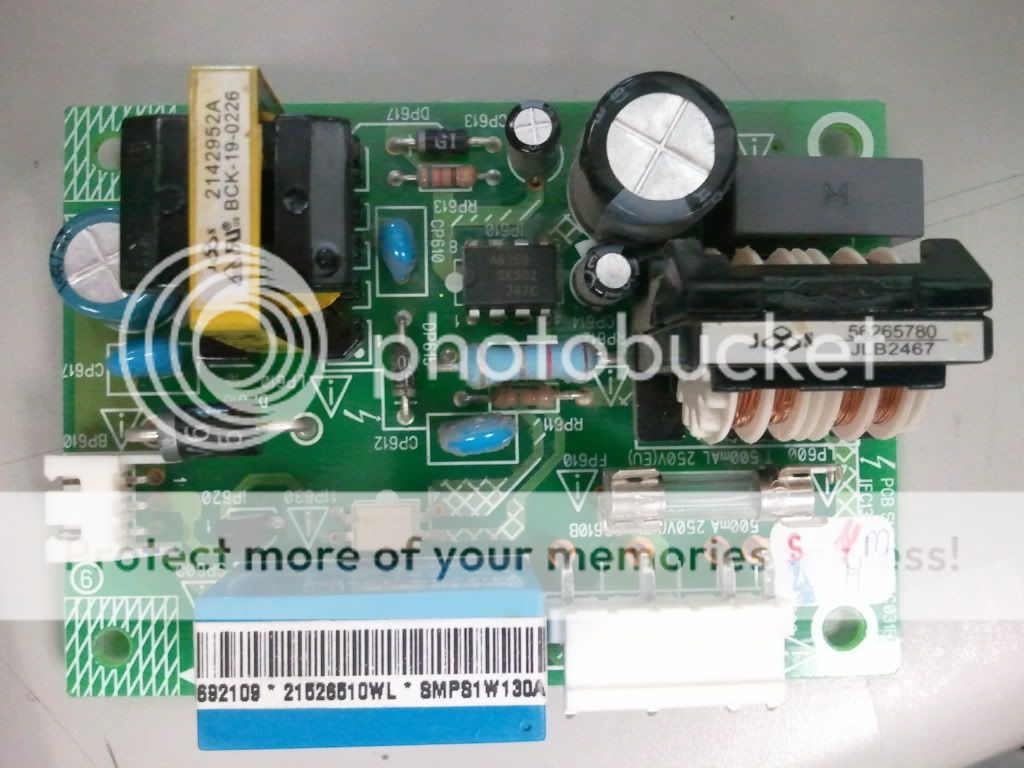
is that a bad solder joint on bp610 or just the picture.Leave a comment:
-
Re: Rca l37wd12 lcd tv
How is the 22uf 200Vdc cap for the primary side checked out? Very good clear pictures! What do you use for lighting?Leave a comment:
-
Re: Rca l37wd12 lcd tv
I will try a higher value resistor. I have the board with me at work and I measured the 470uF output cap, measured as 300uF.
Here are a couple pictures, there's no solder on the one cap because I had it out for measurement.
The 470uF 16V cap is a Lelon (?) 85°C H545 (M)
The other large cap is an Elite 22uF 200V 105°C ES(M)

Leave a comment:
-
Re: Rca l37wd12 lcd tv
It is labelled "1W board". Maybe try 20 ohm as budm suggested or even 25-30 ohm... It could be current limiting. (I think I got a little confused when I worked out the power dissipation of the resistor, it's V^2/R.)Last edited by tom66; 05-09-2012, 12:49 AM.Leave a comment:
-
Re: Rca l37wd12 lcd tv
Diagram, should be close to what you have, the TL431 is the ref Diode and part of the feedback.Leave a comment:

-
 Hi and thanks in advance for any input you might provide!
I have a Sceptre U550CV-UMRD8POTV83BB 4K LED (this is a dumb tv) that I bought new in August 2021, so It's just completed 3 years.
Main power board model: TP.MS3683.PC821 T-Con board: N4TP546UHDPU2L_BO
Last Sunday I was watching a dvd and fell asleep for about half hour, when I awoke the tv screen was black and couldn't get the dvd menu to show, so I changed the input to antenna and had sound but no picture, turned it off. I then got online and found this great site! ....read many troubleshooting tips and this... -
 Hi everyone,
I’m looking for help with a persistent issue on an LG TV model 55NANO77SRA, which uses the main board EBU66792103 (also used in LG UQ80 and NANO75/NANO80 series).
🧩 Problem Summary:- The TV keeps scrolling through the menu or selecting items by itself.
- I removed the physical button board (the entire panel with power and volume buttons) and also disconnected the flat cable (CN202) from the main board.
- The remote control is not in use (batteries removed), and the TV still shows the same behavior.
- I
07-28-2025, 08:34 AM -
 Hey guys great forum glad to have found it. I bought a Sony XBR 65X900C cheaply because it didn't work. No signs of life at all not even a light/led. All I hear is a brief high voltage sound when I throw the power to it.
Didn't see any obvious signs of damage so right away started checking voltages. This is what I see:
Power Board Connector that goes to Main board
CN6401
Pin 01 NC
Pin 02 NC
Pin 03 "BL_ON": 0V
Pin 04 "N/C"
Pin 05 "STBY 3.3V": 3.5V
Pin 06 "GND": N/C
Pin 07 "AC_OFF"... -
 ONN 100012588
Issue: No Power, Then Rebooting After Main Board Change
Short answer: replace main board and power board
Technical answer: replace main board and Q306 & Q307 on power board.
Long answer:
TV wouldn't turn on. Power switch was fine which means the main board isn't processing the power on signal. Replaced main board. TV turns on now but randomly reboots. Bad main board? EEPROM? Tried to pull main board and got a shock touching the corner of the board. That's weird. C334 (450V 10uf) capacitor is still holding a high charge.... -
 Hi, this is my personal laptop, which the original board (lets call it Board A) blew up PU8700 (TPS51486), making a hole on the board, i had left the laptop at my desk one day with the battery fully charged and didn't touch it for a week, but when i tried to turn it on it didn't
Thought the battery was dead, so i plugged in the charger then tried to power on, the power LED blinked once, charged LED still orange, unplugged the charger, plugged in again and I noticed the "magic smoke" smell, so i unplugged the charger, removed the back cover and saw the blown IC (the "magic...
Leave a comment: