-
Good job, glad you concentrated on getting another mainboard, SO many times people let a bad replacement board allow them wander off in the wrong direction.Leave a comment:
-
Just a follow-up. I replaced the main video board from a different supplier. The TV works again.😅😅😅
Many thanks everyone for the help on this.
Leave a comment:
-
OK, watching the circuit it's a reset chip, but top right pin is strange at around 0v, if you are able to remove this chip without damaging it you can after it power the set and with a scissor or wire perform a reset between the pads of the switch solder place..Leave a comment:
-
-
-
Now is 100% clear, so the power board is ok, all readings are within specs, Vamp is Audio amplifier voltage and is ok at 13v, the ic905 is wrong if is a voltage reg. , tell me the marking code, it has input 5 - O volt but output must be 3,3v i guess..Leave a comment:
-
Davi,
Here are the readings for all 14 pins from the power board. These readings are between ground and the pin with power on the board. For reference, I also show the pin map print on the board. The pins that I see are out of range are Pins 2 and 14. I am not sure what Vamp is, so 5 and 6 might also be out of range.
For the IC905, I have remove the IC901 but here are the IC901 volt readings.
Leave a comment:
-
-
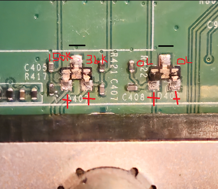
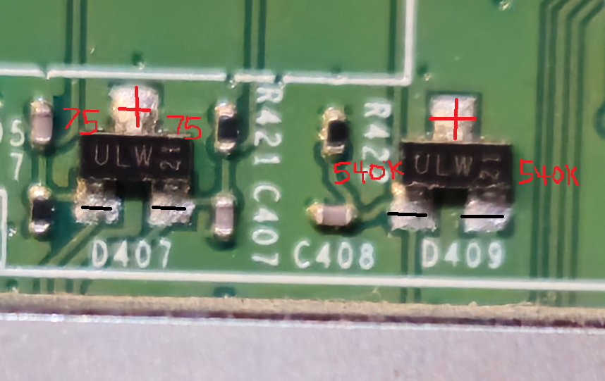
both things wrong.. in the early posts you tested only odd pins, pins are in 2 rows, you wrote the signals marking as them are one only thing but are 2 signals in a row, power on-off is one thing, A5v is another and you are measuring A5v only..
second thing, i want you to bear with original board for now, checking ic905 i mean the pins voltages respect to GND, i guess this is a voltage reg. but not sure, tell eventually its code..Leave a comment:
-
If it was me, I would try another mainboard, sometimes you get a bad one, you should be able to get a refund.Leave a comment:
-
-
-
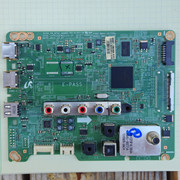
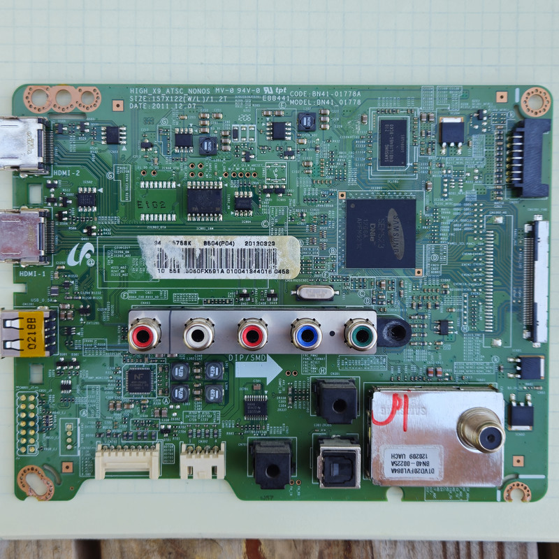
Going to give it my best guess, tho I don't like guessing. Some possibilities, may have bought a bad mainboard or damaged in transit or mis-handled, mainboard may not be a match, can you show good focused picture of both boards, WHOLE board not just the damaged part.Last edited by nomoresonys; 07-17-2024, 05:52 AM.Leave a comment:
-


-
 Hi,
Hi,
I’m trying to fix an HP EliteBook 840 G6 that stopped working after a lightning storm.
– Charger is OK and 19V is present at the motherboard.
– No charging LED, no fan, no reaction.
– I don’t see any 3.3V or 5V near the coils.
– Battery is unplugged.
– I’m new to board repair but can use a multimeter.
I added a clear photo of the board.
Any idea where to start or what to check next?
Thanks a lot for your help!...07-01-2025, 10:45 AM -
 Yes it's a 17 year old Panasonic plasma!
I was watching TV when there was a huge lighting strike nearby my house that shook the house. When that happened, the picture on the TV froze and the TV wouldn't turn off except by pulling the power cable. Now if you plug in the TV, it seems to turn on (it makes the turn on "clikcs" it always does, the red power light comes on but there is no picture, although I can see the back light around the edges. And the TV doesn't respond to the power button on the remote to turn off, and doesn't respond to the manual power button on the front... -
 THE LIGHTNING:
This was a very close strike, blew a 15 amp breaker for all ceiling lights in home AND could smell ozone for a few minutes after strike.
Very close and probably a very strong EMP.
THE TV:
No standby LED. Some voltage from PSB (not totally dead).
But found a kit of ALL 4 circuit boards for $55.
At first thought, this will fix my TV.
But then lightning has the ability to totally fry semiconductors. Which would include any or all of the PCBs. However, the display is one big semiconductor and given... -
 hi everyone,
my parents in law have seen their Bravia Sony LED 32EX600 TV set stop after a lightning strike. After being plugged to mains, it shows nothing no power LED on bottom left shines.
On the power PCB (GE3b, attached pic), I chacked the fuses and the only roasted one is R6536 : 0.47 ohms, 1/2W. After replacing it, I made some voltage measurement with ref to the chassis :
- the 450V/150uF capacitor voltage when plugged is normal at 394V
- from connector CN6150 (15 poles)
STBY normal 3.3V -> I shunted it to 3 (POWER ON) and 11 (BL ON) and unplugged...06-28-2023, 02:43 AM -
 Hello Everyone.
This powerful amplified subwoofer doesn't make any sound after lightning striked near the house were it was plugged in.
It consists in :- a power board were the full H bridge class D amplifier and main power rails are located
- a preamp board (ref. F.01U.299.771) receiving 2 symetrical inputs(IN1, IN2), a digital chain (A-D converter -> Digital Signal Processor -> D-A converter) and a micro controler in charge (at least) of the human interface (lcd display and 1 rotating button)
human interface is working fine
Input levels are...01-23-2024, 10:21 AM
Leave a comment: