Re: Fish Tank LED Power Supply Gets Hot then shuts down
If you have vibration on the wires then make them a little longer and put it in a one loop circle so it has room to vibrate I done this in the past and sometimes it gives you good results
If the wires vibrate it will usually break at the end of soldering as where it has made the wire stiff and that where they break apart
One other note if you use wires that many more strands ( very fine small diameter wire ) of wires you are better for this type of environment yes this type of wire is more expensive per foot but is much better wire and harder to find but you can use automotive type battery wiring
Something like this type of wire
AWG Gauge Marine Grade Wire Boat Cable Tinned Copper EBay
https://www.ebay.com/itm/17451973904...Bk9SR8y7yrWAYQ
I hope this helps you with this issue
-
Re: Fish Tank LED Power Supply Gets Hot then shuts down
Well like I said, those connectors are VERY strong ... sometimes I have to use some pliars just to get the lever pulled back all the way to fit a larger gauge wire into it but when it clamps down, the wire isn't going anywhere and vibrations wouldn't shake it loose either ... you'd have to see these for yourself to understand just how strong they are.Leave a comment:
-
Re: Fish Tank LED Power Supply Gets Hot then shuts down
It's not tugging force that's the problem, it's vibration...Leave a comment:
-
Re: Fish Tank LED Power Supply Gets Hot then shuts down
The alternative is solder and heat shrink and making cables that have to split into many directions using that method is less than ideal. Also, those connectors that I have that solder directly to the circuit board have grabbing strength that is extremely strong. I think they could easily withstand 50 lbs of tugging force or more. I've tried pulling wire out of them manually before and I couldn't do it.Last edited by EasyGoing1; 10-21-2022, 05:47 PM.Leave a comment:
-
Re: Fish Tank LED Power Supply Gets Hot then shuts down
A large number of wires just soldered onto the board is sloppy design especially if it's not restrained from movement, even if it wasn't intended for movement. Shipping is movement...Leave a comment:
-
Re: Fish Tank LED Power Supply Gets Hot then shuts down
Funny you mention that as about an hour ago I was contemplating whether or not I should replace the internal wiring, or at a minimum, everywhere there is exposed wire where it solders to a PCB (wires from the PSUs that is), remove the solder, clip the ends and re-strip them and re-solder.
But, this is where I stop thinking that it had anything to do with the wiring at the three LED driver boards ... the burnt wire was burnt all the way from the LED driver board to where it connects on the main controller board, then we have burn marks along the main controller board ... so the actual source of the high current drain on that +12V line could not have been caused by any mishap with the wiring from the PSUs ... there had to be something on that controller board that was drawing too much current but I can't find anything that is not working on the main controller board and so ...
I wonder if a situation like this happened...
The light mounts to a large fish tank which means that condensation - especially when the unit is not powered on, is a high possibility ... so like what if they left the unit off for a long time ... maybe days ... and some condensation builds up on that main controller board and creates a temporary short somewhere on that board so that when the unit is then turned on, that short burns the board, melts the wire, damages the PSU and in all that chaos, the moisture that caused the short gets boiled off from the heat it caused.
Then from that point forward, when they try to turn the unit on, it only turns on for a second or two and that damaged PSU goes into thermal over-heat protection mode or it just straight up stops providing power but remember the heat sinks in that PSU get too hot to touch within seconds after switching it on...
But a temporary short would explain the high current while also not having any failed components on the main controller board.
YES, the 7805 still gets hot, but that will be mitigated with the constant airflow going through the enclosure so that could actually be operating within design specs.
It very well could be that the solution this whole time is just to replace the melted wire and the bad PSU.
I'm pretty sure I could test this theory by testing the unit with only one LED panel at a time. After connecting one panel to the good PSU, and powering the controller board from my bench PSU, if everything checks out, then I swap that LED panel with the next one and test it, etc. until all three are tested and proven to be working.
If that works, then I can take measurements to find out just how much current this damn thing really consumes and spec a power supply accordingly.
Also, if it turns out that I'm right about how this unit failed in the first place, I do want to replace the two power supplies with a single power supply and mount some kind of wire distribution panel inside the enclosure where the one PSU feeds that panel and then it breaks out to the driver boards and the controller board.
This PCB I threw together could work for that distribution panel and it only costs $22 delivered within 5 days. I could also add jumper points and include an inline fuse for both the 5 and the 12 volt lines and mount the fuses on the outside of the enclosure so they would be easy to replace if they blew. The current measuring points was just an idea I had ... not sure if Id keep that or not, but certainly would use a similar layout for the fuse idea.
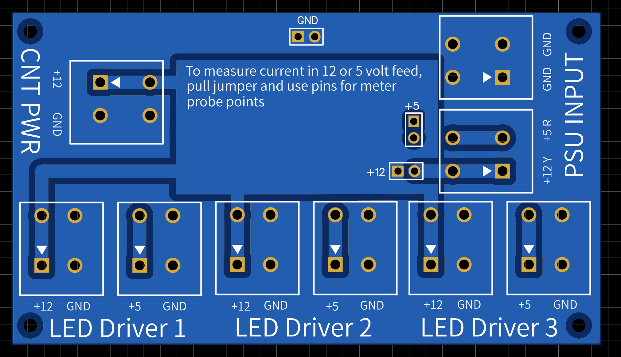
Here is a 3D view
Leave a comment:
-
Re: Fish Tank LED Power Supply Gets Hot then shuts down
lcd displays draw about 1.5mA without the backlight,
the backlight varies by design, some are a bar of leds while others are just end-litLeave a comment:
-
Re: Fish Tank LED Power Supply Gets Hot then shuts down
You never mentioned that it was 5A when the LEDs were turned on. It was implied it was drawing 5A when off, which is a problem.
So now the question is how much current is being drawn on the 12V line. Is it normal? Why didn't you just replace the wire assuming it was just a short at the board due to poor manufacturing?Leave a comment:
-
Re: Fish Tank LED Power Supply Gets Hot then shuts down
I have at least FIVE of those exact same LCD displays that I bought in a cheap group from Amazon just to have some, I'll fire one up and see what kind of current it draws ... though it will be a unit that is close to 20 years older in design than this one, but I can't imagine they have changed all that much. They look identical except for the connection methods.
I think this is where everyone responding to this post has gotten confused. I tried to spell it out as detailed as I could, but admittedly I've posted a lot of information and even had to correct some mistakes so lets cover that right here and now...
The power lines that come in from the PSUs are of course of two types: +5v and +12v
The 5 volt lines ONLY DRIVE LEDs ... the 5 volt lines have NOTHING TO DO with the main controller board OR that wire that melted.
The wire that melted is a tap on the +12 AND GROUND from one of the PSUs, and that wire directly feeds the 7805 that powers the main controller board.
So whatever melted that wire, was from a high current draw on the main controller board. Now that could have been a fan that went bad (as one of them wont power on at all, and it is not shorted either, but I did see that the ground cable on that fan was disconnected at the fan itself and there was some obvious corrosion around those connection points. The wire was soldered onto a PCB at the center of the fan, but it just somehow broke off at the solder point. When I barely tugged on the red wire on that same fan it also came off of its solder point ... since this light assembly sits above a fish tank 24 / 7, moisture is going to be an issue and if its a salt water tank, then that will be even a worse problem.
BUT even though that fan went bad, none of the fan wires were melted or showed any kind of problem at all.
The only damage that we see, is the melted wire, which carries +12 AND GROUND from the PSU to the 7805 on the main controller board. Then on the main controller board, we see burn marks on the PCB directly around the 7805 and also at various points along the GROUND TRACE on the under side of the PCB ...
I want to throw out this thought concerning the +5 and the amperage I saw it taking when I connected the unit to a PSU ...
At that time when I took that reading, I had not taken apart the main unit. So I have no idea which of the two PSU lines inside the unit I was taking that reading from. As one PSU line is split off inside the housing and those lines are connected to TWO LED panels. And those PSU wires go no where else. The other PSU wire connects to the third LED panel but its +12 is tapped to power the main controller board.
Now since +5 ONLY powers LEDs and those LEDs are in parallel, I am suggesting that the amperage we saw might be just fine if we assume that those LEDs can suck a lot of amps... powering 10 sets of two LEDs in parallel (on one PSU and then only 5 sets of parallel LEDs on the other PSU) could add up to 5.5 amps if I was connected to the LED panels that drive 10 sets of two in parallel ... if one set of parallel LEDs consumes only 400ma we're close to 5 amps already. I have LEDs that I can drive safely at 250ma PER LED ... two in parallel is half an amp, then ten of those is 5 amps.
I don't think the +5 amperage issue is of any concern ... the real problem is what happened along that +12 that feeds power to the main controller board - and the evidence for that statement exists in the fact that those wires were melted and there are burn marks on the board that those wires feed. There is no other damage anywhere else in the entire unit. No damage at the LED panels or their driver boards and I did check all of the LED strips and nothing is shorted ... I checked all 15 rows of LEDs and confirmed that they are all working properly.
By the way, that blue line that you drew on the graphic is the ground strip that runs along the edge of the PCB. It is electrically equivalent to the ground lines coming from one of the PSUs. But both of the PSUs ground points are ultimately connected together via the pins that drive the base of the TIP141s on each LED driver board. On the graphic you drew the line on, the final resting place of that ground line is the last pin on the connector(s) that drive the base on the TIP141's on every LED panel.
At the top of that graphic, that last solder point is the end pin on those connectors, and as you can see, there are SIX 5-pin connectors at the top of that board and on all six of those connectors, every single pin is electrically equivalent to every other connectors pin of the same number.
So all of the Pin1's on those six connectors are connected together. Same with all of the Pin2's etc. etc. so in that graphic that you drew the blue line on ... where it connects at the top, I would call that Pin5 of the connector that goes out to the TIP141 driver boards and that all six of those connectors are equally grounded at Pin5 (this is what connects the grounds together from both PSUs)
This explains what you ask about in the rest of your quoted response here...
Then as we continue ...
I have not and nor will I remove any of the actual LEDs to try and identify them. But here is a picture of one with its housing removed:

And as I just stated, those could EASILY be 250ma LEDs, which would account for the 5 amps we saw being drawn on the +5 line given the that there could have been 10 sets of these wired in parallel being powered by the PSU. I'll say it again, I think the issue of 5 amps being drawn on the +5 from the PSUs is a dead issue and has been sufficiently explained where that was actually never a problem.
This is how sure I am about that ... when I looked up the actual part number, it indicated that it was some TYPE of regulator where they make them in different flavors, but the datasheet also talked about being able to set the voltage and maybe vary it based on the config layout? I didn't want to spend time learning how to use the regulator, so I just connected power to the 7805 then took voltage readings from the regulator right next to it and it does indeed kick out a steady 3.3 volts.
Also, I just now traced out the 3.3 volt output from that regulator and it stops at one of the pins on the ribbon cable that connects to the LCD display so that must only power the LCD display and not the microcontroller as I previously assumed. Im sure that MC chip is a 5 volt chip as you suggested.
FOR THE RECORD
I think that we can ignore the 5 amps being drawn on the 5 volt line and now focus on the real problem which is the melted +12 wire and the directly connected burn marks on the main controller board.Leave a comment:
-
Re: Fish Tank LED Power Supply Gets Hot then shuts down
I think the LCD display backlight is a hog, 260mA at 5V is a 1.3W load which is lots for a character display. They are usually around 100-140mA. But maybe it's an older display or the backlight has a problem. This high current drain will naturally cause the 7805 to run hot, but it's got fan cooling so I think it's not a problem to go after yet.
I would say the original problem, the short-circuit causing overcurrent on the melted wire needs to be tracked down first. That's why I was asking to check the LED's for ground-faults, especially on the panel that doesn't light up and those powered from the main PSU 5V where you see the mystery 5.5A load. You can look at the LED's for burn marks or black spots too, shining a light in their lens.
Also, I can't see the end path for the hot pcb trace on the controller board, this is strange. Follow the blue line from J3 to whatever. It should have fused/melted the little traces if the LED driver boards were pulling high ground current - wait... I suspect it must be the first connector (board) that was drawing the high current. I suspect this one connector leads to the shorted culprit.
The LED's are likely a 1W or 3W part? So roughly 75 LED's which is around 75W or 225W and I can't see needing two AT PSU's to power this. It's gotta be really bright.
edit: you sure about a 3.3V reg? This board is from the 5V era, the Z8 etc. I think is 5V powered.Attached Filesif you find these attachements useful please consider making a small donation to the site
Last edited by redwire; 10-20-2022, 04:56 PM.Leave a comment:
-
-
Re: Fish Tank LED Power Supply Gets Hot then shuts down
check the lcd display for partially shorted caps and see if it has any resistors in series with the backlightLeave a comment:
-
Re: Fish Tank LED Power Supply Gets Hot then shuts down
The cooling fans are only switched on or off by the +5V rail on the main controller board. Their actual power comes from the +12v rail which has no bearing on the current flowing through the 7805. They are also pulse width modulated based on the ambient temperature that is read with a thermistor mounted by the microcontroller, but switching them on or off or even pulse width modulating them has essentially zero impact on the current being drawn through the 7805 since that current is only in the context of the microcontroller and it simply switching pins on or off very rapidly.
So I'm not sure where to look for a short since the mainboard is working though I still have not re-assembled and tested with the LED panels connected, which is good since the issue here is manifesting without the LED panels being included.
Where would you suggest I look? Because what you seem to be telling me is that I SHOULD expect a 7805 to heat up to 67C when it's only passing 260ma from a +12v source... is that in fact, what you are telling me? OR are you telling me that 260ma is too high for that LCD display and that it should be drawing much less current than that?
Edit: ALSO, When I connect the main controller up to power with JUST the LCD screen attached and I turn the LCD screen backlighting to 0, it draws 170ma ... when I turn the backlighting up to max value, it draws 310ma total at the 12 volt source.
I also noticed that when I had the fans connected and they were merely in proximity to the 7805 such that there was a small amount of air flow around it, the temp of the 7805 dropped to about 45 to 50C and stayed there, and when this thing is all put together and operating there will always be air flow moving outside air in and through the entire enclosure and that cannot be changed via the interface. There is an option to override fan speed but your only options are Automatic speed control or all fans at 100%.Last edited by EasyGoing1; 10-20-2022, 02:44 PM.Leave a comment:
-
-
-
Re: Fish Tank LED Power Supply Gets Hot then shuts down
Since 5V from the PSUs are only connected to the LED boards, I suspect one of the boards have a shorted transistor+one of the two parallel LEDs on the board. Search for it... disconnect them to help find the defective boards?Leave a comment:
-
Re: Fish Tank LED Power Supply Gets Hot then shuts down
OP has to find the short-circuit or this is a waste of time. If the ground trace to the controller board goes open-circuit it would damage the board with ground getting lifted up.
I think the 7805 current is high, not sure what the extra drain on that 5V rail is, the second TO-220? It might switch the backlight LED off.
But this thing isn't put together with the cooling fans running, so maybe it's OK.Leave a comment:
-
Re: Fish Tank LED Power Supply Gets Hot then shuts down
Is the whole system still drawing 5A on the 5V line? 260mA on the 7805 is not 5A on the 5V line...
Though 67°C is hot, and may start derating, it's probably fine and about what it's expected. 7805 are sturdy and usually won't kill themselves when they are overloaded. As long as you're getting 5V on the output, it hasn't shutdown.Leave a comment:
-
-
Re: Fish Tank LED Power Supply Gets Hot then shuts down
Junction Temperature
The maximum operating junction temperature is usually 150 ºC for 7805 voltage regulators, and operating at the maximum will certainly affect the reliability of the device. The recommended operating junction temperature is usually 125 ºC. This figure tends to be the same for the majority of silicon based voltage regulators in a TO-220 package.
Ambient Temperature
The ambient temperature is the maximum temperature of the surrounding area that the device will encounter. It is usually 25 ºC; however, you have to consider the worst-case scenario. In the summer, the temperature can go as high as 30 ºC, and if the airflow was poor then a figure as high as 60 ºC is more appropriate.
from here ...
https://www.petervis.com/electronics...Regulator.htmlLeave a comment:
-
Re: Fish Tank LED Power Supply Gets Hot then shuts down
... so given the size of the 7805 with its heat sink, and considering the fact that this 7805 is BRAND NEW ... and the fact that it's heating up to 67C including the entire heat sink ... while only drawing 260 ma from a 12-volt source ... DO WE HAVE A PROBLEM? Or can I just replace that 7805 with a buck converter and call it good?Leave a comment:


-
 I have here a Magnum IA.100 which belongs to my parents.
The unit powers on & when the relay kicks in, you get a pop from the speakers (this might sound weird but is usual behavior for this amp). However, you get nothing coming through it from any of the inputs & no pops and crackls from any of the controls.
Because of the sound from the speaker when the amp turns on I have assumed that the output section probably works but I could be wrong & I'm not sure how to test that side of things further.
What Ive done........01-01-2025, 01:26 PM -
 Hello
Hello
Laptop E15 I5 10gen
Mb nm-c421
I have a problem with the usb-c power dc.
The motherboard start only in one side of the usb-c
Replace the usb-c port 2 times same problem
With the usb-c meter, one side 20v ok, other side the usb-c meter don't come on
Try to test the pin with the Mechanic Tail insertion tester and every pin are ok ?
Can the pd controler be the fault ? Or something else maybe ?
Thx
... -
 The model is 15ec-1061nm
Board number is DAG3EDMB8D0
SO i turn the laptop on , and as soon as it starts booting from disk, from usb, windows,linux,HBCD,anything i boot it just turns off....while in bios menu or in linux boot menu it stays on normally...It's like when it starts to use graphics it shuts down...But i measured 0.72V while working on the GPU power line,no excess heat is comming from GPU or CPU, i even removed the heatsink and turned the laptop on and everything worked fine, got a bit hot, fan span to full speed, but it worked like that for few minutes in bios...10-29-2024, 12:05 AM -
 Hello everyone,
I have a Lenovo V15-IKB that had a damaged motherboard. I replaced it with a motherboard from a Lenovo V15-IIL.
The board powers on, but it shuts down after about 10-15 seconds. This only happens when the internal display (LCD panel) is connected.
Here's what I've tried so far:- When the internal display is disconnected, the laptop works perfectly fine via HDMI.
- The laptop shows an image on the internal display for a few seconds before it shuts down.
- I tried swapping the LCD panel with a known good one.
- I tried swapping the LCD cable
-
 Hello everyone,
I need help with my Lenovo Legion laptop. It turns on for a few seconds and then immediately shuts down. I believe this is a BIOS corruption issue.
Laptop Model:- Model: Lenovo Legion Slim 5 16APH8
- GPU: NVIDIA GeForce RTX 4070
- Main BIOS chip size: 32MB
- VBIOS chip size: 16MB
What I Have Tried So Far:- I
11-04-2025, 05:14 AM
Leave a comment: