
Re: Fish Tank LED Power Supply Gets Hot then shuts down
Wild guess is the +5VDC rail powers only the red LED(s) and one has shorted to the heatsink and thus chassis ground.
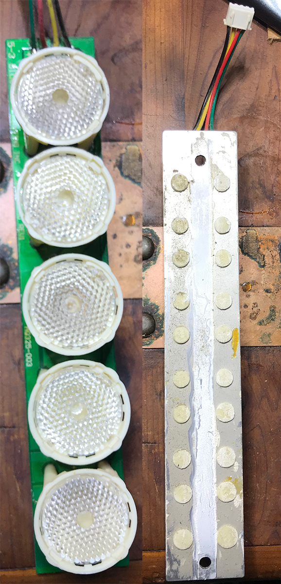
I would say you need to test/study the LED boards a bit more- 5 LED's, 4-wires is weird. It might have 2-red because they are dimmer than blue or green. What colour mix are on a board could help solve the puzzle.
It must have artificial sunrise/sunset capability, thus the need for an RTC and ability to control colour.
-
Re: Fish Tank LED Power Supply Gets Hot then shuts down
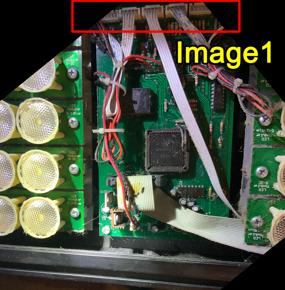
This might help you in understanding how the 5v line from the PSU connects to the main controller board
That line from the LED Driver to the main controller board are the wires that melted
 Last edited by EasyGoing1; 10-13-2022, 02:00 PM.
Leave a comment:
-
Re: Fish Tank LED Power Supply Gets Hot then shuts down
You might be right about dimming the lamps ... that might be controlled from the access panel (the user interface LCD screen) which goes to the MC and then that would mean that the MOSFET chip (TL084IN) is actually driving the driver board mosfes and the gates from the TL084IN are controlled by those digital pots that are controlled by the MCLeave a comment:
-
Leave a comment:
-
-
Re: Fish Tank LED Power Supply Gets Hot then shuts down
Just a side comment aside from my detailed response to STJ, is that after my basic examination of this unit, I remain kind of puzzled to understand how an aerospace company managed to get a patent that was obviously close enough to the design of this device that was then leveraged to put this company out of business.
Nothing I've seen about this design so far appears to me to be anything other than typical circuitry that drives power to these LEDs.
Now I don't know anything about the LEDs specifically, nor do I understand how anything about this unit makes it uniquely applicable to fish tanks, UNLESS there is something about the code inside the microcontroller that provides the "magic" that makes this device somehow a device that is beneficial to marine life. Because outside of the microcontroller, all we have is typical voltage controlling via MOSFETS as would be the case in any LED driver environment.
Yet, the patent and the action against this company did happen so clearly I'm missing something but that something must exist in the microcontroller since the LEDs - Im assuming - are most likely something that can be purchased by anyone and were not manufactured by this company.
Leave a comment:
-
Re: Fish Tank LED Power Supply Gets Hot then shuts down
And do we need to back up to the first post that the LEDs work just fine with one PSU and not the other, so technically the LEDs should be fine and just need to figure out why it needs 5.5A... when the LEDs are on or off? Is the MCU/LCD working?
Are those LED units 3S (so the individual 5-LED boards are actually 3S5P?) I still can't really see a good reason to run the LEDs off the 5V line but who knows how they designed it to balance the use of the power coming from the PSU ...Leave a comment:
-
Re: Fish Tank LED Power Supply Gets Hot then shuts down
but are the led drivers running from 5v or 12v?
the controller must be 12v or it wouldnt need the 7805 regulator.
i suspect you program the unit over the serial port and it can dim the lamps at different times using the clock chip.Leave a comment:
-
Re: Fish Tank LED Power Supply Gets Hot then shuts down
So there are three aluminum heat sinks, each with 5 rows of LEDs attached with two screws. The PCBs of the LEDs are aluminum PCBs and the PCB has thermal compound grease on the aluminum side of the PCB.
Each PCB is wired to another PCB that has high-wattage resistors on one side and the four MOSFETS on the other (which I thought was odd because there are five rows of LEDs but only four MOSFETS).
Lets call those PCBs the LED driver boards...
The PSU lines come into the unit and are soldered onto the first driver board then they are connected to the other two driver boards in a daisy chain fashion but from a schematic perspective, they would be wired in parallel.
Then from the last driver board in the housing, that 5-volt feed from the PSUs is soldered to those two wires that melted and attached to the main controller board via J3 as shown in the photos. J3 feeds the input of the 7805.
From that main controller board, there are two voltage regulators. The 7805 and a 3.3v regulator (the input of the 3.3v regulator is fed from the output of the 5v regulator), which powers the MC. There is an RS-232 chip that feeds a connector which looks like it is used to program the MC, and there is a chip that is just MOSFETS (ST TL084IN). Then two small square chips next to it (CSI 5114V) that look to be digital POTs.
The outputs from the controller board consist of the outputs that go back to each driver PCB for the lights, which are connected via ribbon cables and those would be driving the MOSFETS that power on the LEDs, then the fan outputs which each of the four fans are home run straight to the main board.
I think that MOSFET chip (TL084IN) actually drives the fans ... I don't think it has anything to do with controlling the LEDs ...
The damage to the main controller board is primarily around the 7805 and along the ground strip on the edge of the board that rides along the MOSFET chip and the digital POT chips that are next to it and that damage even managed to burn off a piece of solder mask on the board.
I checked all four fans, and three of them work. At 12 volts they are drawing 140 ma ... the fourth one does not power on at all and it is not drawing any current.
Nothing I've seen so far, explains why the 5 volt line is drawing 5.5 amps from the main PSUs ... unless there is something about those two MOSFETS on that last driver board (showing some kind of damage to them) that is the same board used to feed the 5 volt power to the controller board ... I can't rationalize how those would be in any way related electrically so Im not really sure what to think about that ... I might need to remove that board entirely and trace it out to see how things are connected but mixing that 5 volt line with those mosfets makes no sense since the mosfets drive power to the LEDs only (at least that is the assumption)
Also, the more I think about it, it makes sense to me that the small digital pots are manipulated by the MC which are then used to control the gates of the TL084IN - giving the unit the ability to control the speed of the four fans... the only thing about that is that I cannot see any kind of temperature sensor that it would use to determine how much power to give to the fans. The only temp sensor that I can see is one that sits a few mm above the microcontroller. But there might be a temp sensor on the driver boards that feed back via the ribbon cables to the MC ... but I'm not sure about that yet.
Last edited by EasyGoing1; 10-13-2022, 01:11 PM.Leave a comment:
-
Re: Fish Tank LED Power Supply Gets Hot then shuts down
before we get sidetracked,
where does the 5v and 12v from the psu go to?Leave a comment:
-
Re: Fish Tank LED Power Supply Gets Hot then shuts down
The red and black wires go to the main controller board (not the red and black wires in this picture ... the ones that fried) and provide it power via the 7805 ... and here is a picture of one row of lights but they are all like this ... soldered on one side only, the other side is aluminum and screwed down to a heat sink.
Leave a comment:
-
Re: Fish Tank LED Power Supply Gets Hot then shuts down
I'm thinking +power goes to the LED's, so I would make sure the LED base is not shorted to the heatsink. Or an open high current ground wire/connection going back to the power supply. The red LED's don't seem to have insulated mounting screw holes on the PC board.
The mosfets are on the low-side, switching to ground so a short (to heatsink) there would just give power all the time to the LED's, drain-gnd short.Leave a comment:
-
-
Re: Fish Tank LED Power Supply Gets Hot then shuts down
damn that was fast!Leave a comment:
-
-
Re: Fish Tank LED Power Supply Gets Hot then shuts down
OK, the MOSFETS are NOT shorted to their heat sink.
But what I find strange is that the red wire (the slow burning fuse) is actually soldered at the same point where the black wire is soldered coming from the PSU...and the ground wire (from the slow burning fuse) can be seen as the tip of the green arrow is touching it ...
I didn't see any kind of short at that circuit board, though with the wires having been melted, I can certainly see how the exposed wire could have been shorting but I didn't look for that before removing the wire from the main board and jostling it around.
The two red circles are the same solder point from opposite sides of the board
And NO, those white connectors next to the resistors never connected to anything ... in case you were wondering.

Leave a comment:
-
Re: Fish Tank LED Power Supply Gets Hot then shuts down
OK, so using the bench power supply at 9 volts ... set to 5 amps, I have the board removed from the unit with nothing else connected to it and then I apply 9 volts to the 5volt regulator ... the regulator output pin reads 5 volts and the current draw is only .1 amps at the power supply ... so that's .1 amps at 9 volts from the power supplies perspective ... Im assuming that we're powering the MC with that voltage and the other chips on the board.
That certainly seems normal to me ... which means that it would probably become necessary to connect the light panels to see the over-current draw at the regulator???
Remember when the unit was still not taken apart we saw 5.5 amps being drawn on the 5 volt line coming from the PSULast edited by EasyGoing1; 10-12-2022, 03:06 PM.Leave a comment:
-
Re: Fish Tank LED Power Supply Gets Hot then shuts down
J3 is just the DC input to the 7805 5V regulator. With the -ve black wire burning up I think would be caused by a ground fault.
So there is an overcurrent happening between the J3(GND) and power... somewhere. Guessing a fan or LED board or heatsink insulation failed and has shorted to power and the resulting high current is pulling ground return current through J3?
I would look for an open ground wire from the mosfets to the PSU.
Poke around with an ohmmeter and see if the mosfets are still insulated from the heatsink, ground wire did not go open-circuit etc.
It's a bit of a weird failure.Leave a comment:
-
Re: Fish Tank LED Power Supply Gets Hot then shuts down
if the main board locks up the led panels could be 100% duty cycle instead of pwm.
if you isolate the controller and feed 9v into the regulator, does it output 5v? and how much current does it draw?Leave a comment:
-
Re: Fish Tank LED Power Supply Gets Hot then shuts down
OK, here's what I THINK is going on with this thing...
this image shows that there are THREE LED "Arrays" which consists of 5 rows of LEDs that are screwed down to a heat sink.
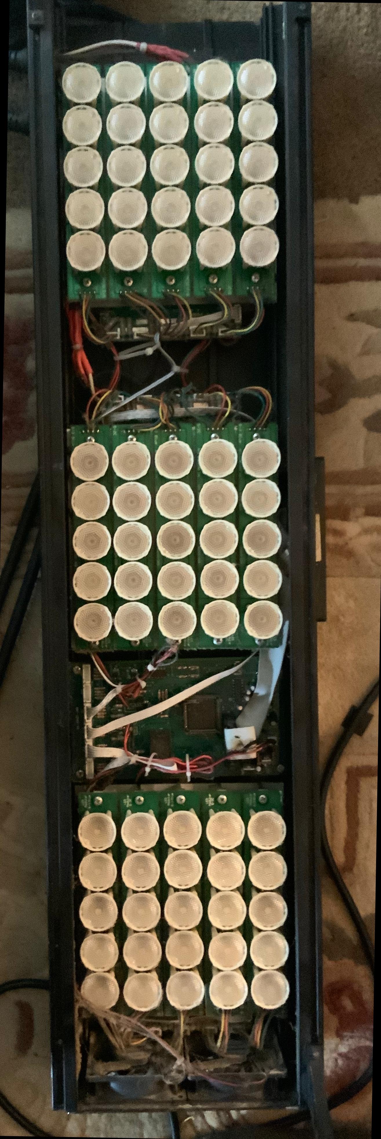
The wires that come in from the two PSUs are wired straight up to the circuit boards that are mounted next to each LED array. Then, we have this controller board...
That feeds each panel by those connectors at the top. ALSO, each panel has FOUR MOSFETS on the underside of the circuit boards attached to each panel and the top of those boards simply have what looks like 2 or 3 watt resistors ... something like 6 per board I think...
I BELIEVE - based on one of the chips I looked up, which was a PWM chip, that the LED panel MOSFETS are being fed a PWM voltage.
There is a wide connector that feeds the display / control screen, and a COM port that was unoccupied.
Heres where it gets kinda weird - at least to me it seems weird ...
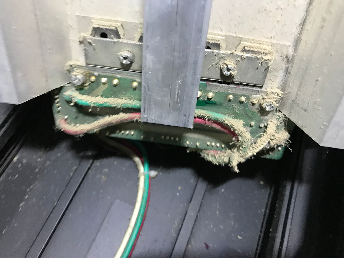
The voltage that is powering the main controller board is taken from the end LED panel and it feeds directly into the input of a 7805 (which has burn marks on the PCB at its solder points) and THOSE are the wires that got their sheathing melted off. And take a look at these two MOSFETS where that power connection feeds from...
The red arrows point to the PSU wires and the two green arrows are pointing to those fried wires which are the power source for the controller board.
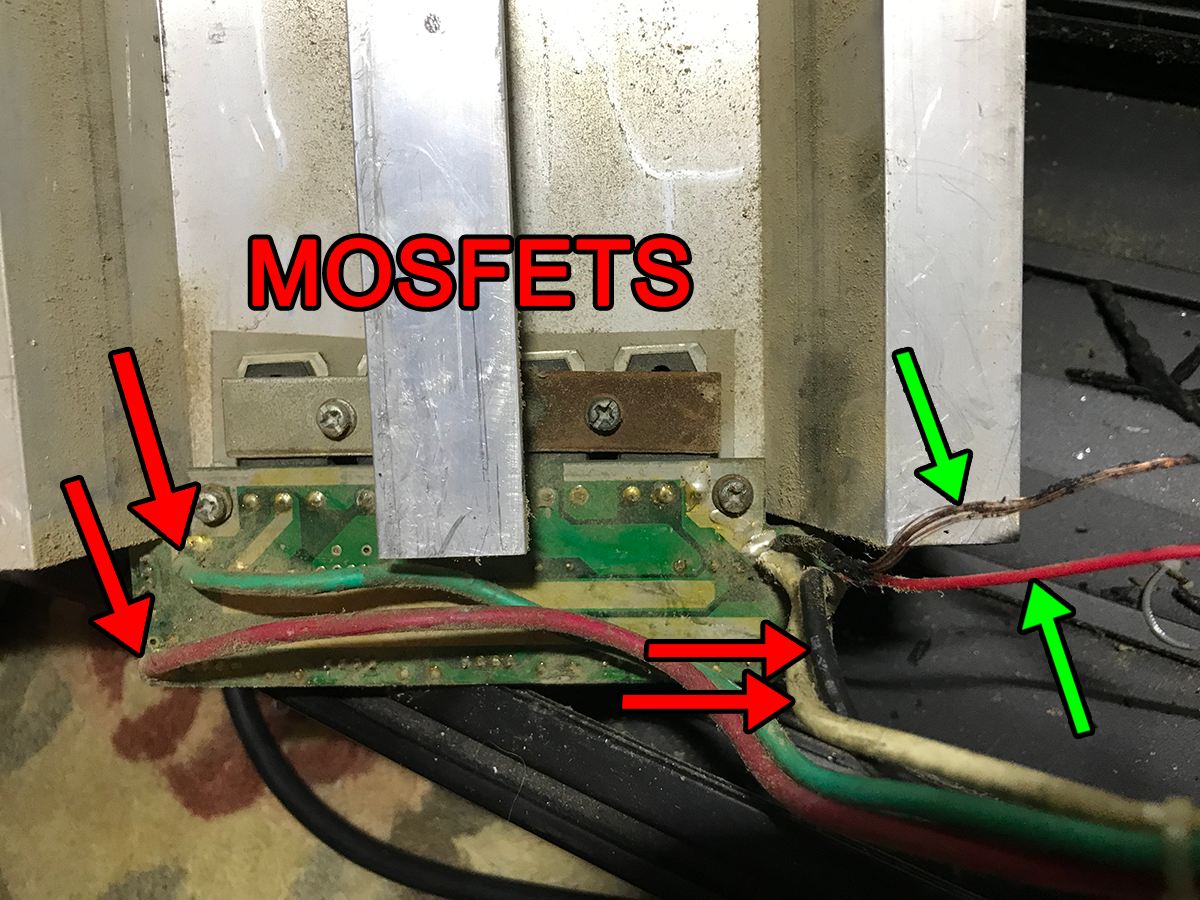
As you can see ... there is major discolleration at those two MOSFETS and it KIND OF LOOKS LIKE RUST TO ME like it got wet ...
Here is one of the other panels MOSFETS and you can see that they have no discoloration at all...
So this is where I'm not sure what to think ... clearly the main board was drawing too much power to that 5 volt regulator but yet the MOSFETS at that LED panel that feeds the power to the main board look suspect to me but they would have no role in powering the main board, they would only be powering the LED panel that they drive ...
So im not sure where to proceed from here...
Leave a comment:

-
 I have here a Magnum IA.100 which belongs to my parents.
The unit powers on & when the relay kicks in, you get a pop from the speakers (this might sound weird but is usual behavior for this amp). However, you get nothing coming through it from any of the inputs & no pops and crackls from any of the controls.
Because of the sound from the speaker when the amp turns on I have assumed that the output section probably works but I could be wrong & I'm not sure how to test that side of things further.
What Ive done........01-01-2025, 01:26 PM -
 Hello
Hello
Laptop E15 I5 10gen
Mb nm-c421
I have a problem with the usb-c power dc.
The motherboard start only in one side of the usb-c
Replace the usb-c port 2 times same problem
With the usb-c meter, one side 20v ok, other side the usb-c meter don't come on
Try to test the pin with the Mechanic Tail insertion tester and every pin are ok ?
Can the pd controler be the fault ? Or something else maybe ?
Thx
... -
 The model is 15ec-1061nm
Board number is DAG3EDMB8D0
SO i turn the laptop on , and as soon as it starts booting from disk, from usb, windows,linux,HBCD,anything i boot it just turns off....while in bios menu or in linux boot menu it stays on normally...It's like when it starts to use graphics it shuts down...But i measured 0.72V while working on the GPU power line,no excess heat is comming from GPU or CPU, i even removed the heatsink and turned the laptop on and everything worked fine, got a bit hot, fan span to full speed, but it worked like that for few minutes in bios...10-29-2024, 12:05 AM -
 Hello everyone,
I have a Lenovo V15-IKB that had a damaged motherboard. I replaced it with a motherboard from a Lenovo V15-IIL.
The board powers on, but it shuts down after about 10-15 seconds. This only happens when the internal display (LCD panel) is connected.
Here's what I've tried so far:- When the internal display is disconnected, the laptop works perfectly fine via HDMI.
- The laptop shows an image on the internal display for a few seconds before it shuts down.
- I tried swapping the LCD panel with a known good one.
- I tried swapping the LCD cable
-
 Hello everyone,
I need help with my Lenovo Legion laptop. It turns on for a few seconds and then immediately shuts down. I believe this is a BIOS corruption issue.
Laptop Model:- Model: Lenovo Legion Slim 5 16APH8
- GPU: NVIDIA GeForce RTX 4070
- Main BIOS chip size: 32MB
- VBIOS chip size: 16MB
What I Have Tried So Far:- I
11-04-2025, 05:14 AM
Leave a comment: