Fish Tank LED Power Supply Gets Hot then shuts down

Collapse
X
 
  • Time
  • Show
Clear All
new posts

  • EasyGoing1
    replied
    Re: Fish Tank LED Power Supply Gets Hot then shuts down


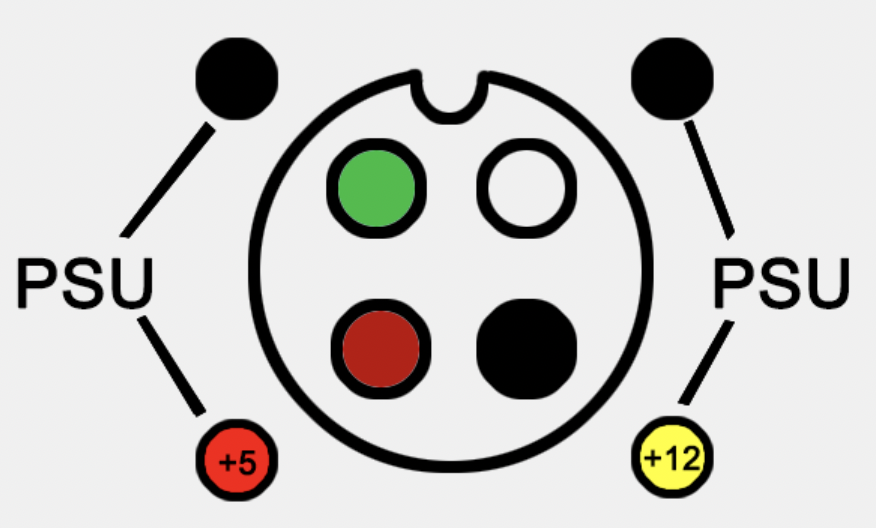
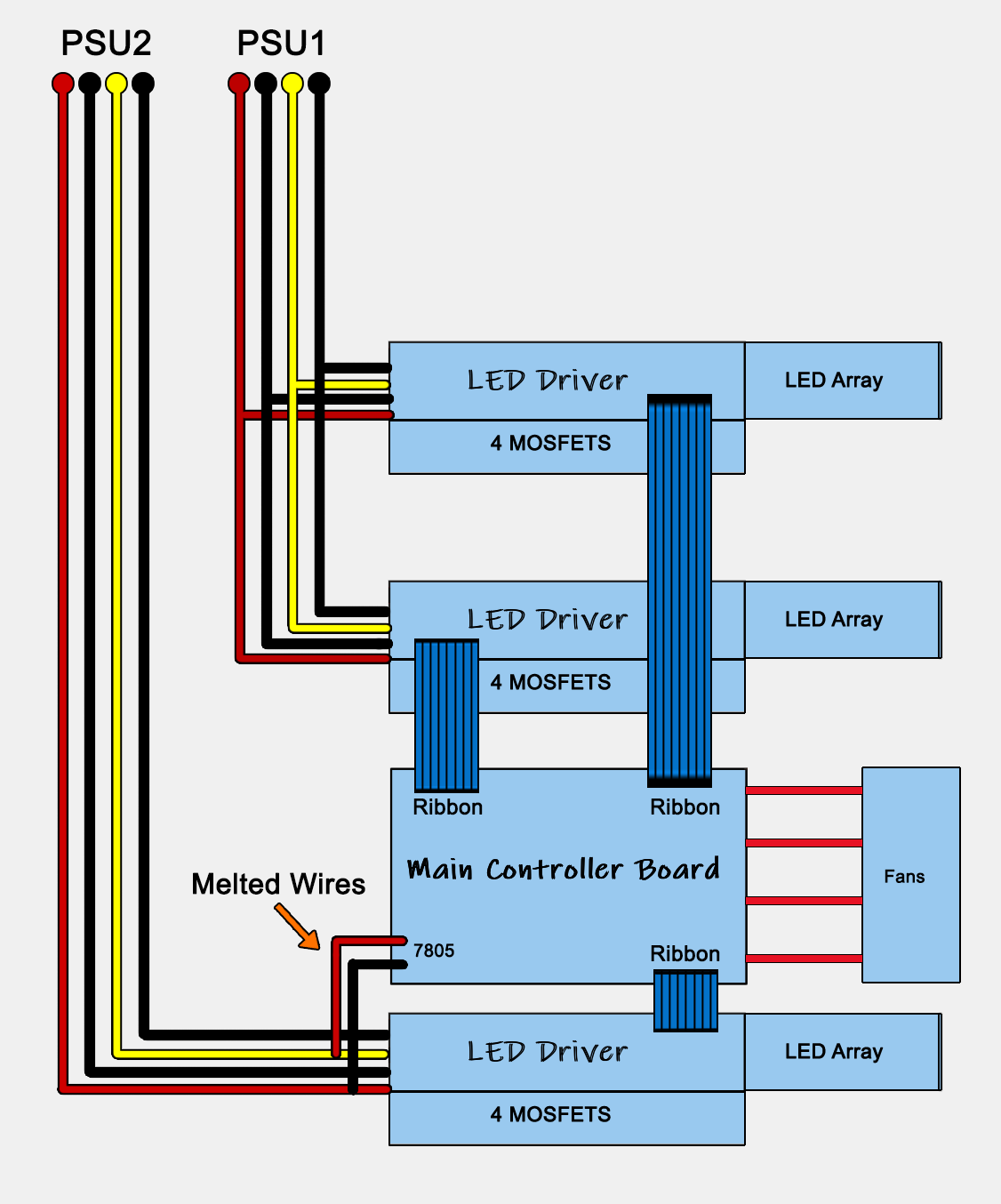
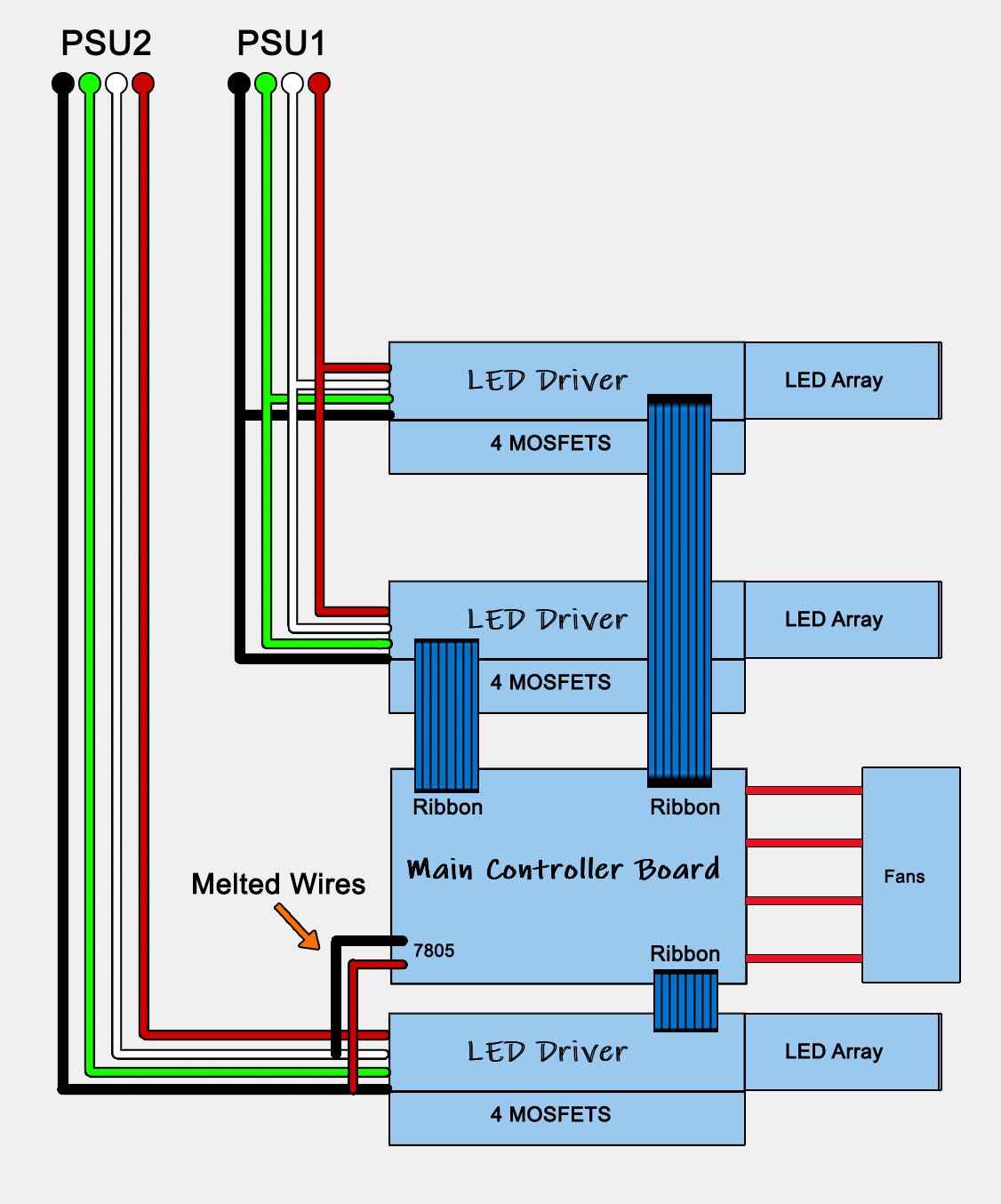
    I was also wrong about the power feed from the PSU to the main controller board. The hotline going to the main controller board is +12, and the black wire is ground from the PSU.

    What's been so confusing this whole time is that the cables they use to connect to the PSU are not the same color wires as the wires inside the PSU.

    But this is how they actually map out, and the melted wires going to the main controller board are red and black, where Red is connected to the black wire which is +12 from the PSU and black is connected to the white wire, which is GND from the PSU:


    Last edited by EasyGoing1; 10-16-2022, 07:12 AM.

    Leave a comment:


  • EasyGoing1
    replied
    Re: Fish Tank LED Power Supply Gets Hot then shuts down

    Here is the LED Driver board schematic ... this shit is kinda WHACK if you ask me.


    Last edited by EasyGoing1; 10-16-2022, 07:10 AM.

    Leave a comment:


  • EasyGoing1
    replied
    Re: Fish Tank LED Power Supply Gets Hot then shuts down

    Originally posted by stj
    outside pair are anodes, inside are cathodes

    it probably has it split to reduce load on the mosfets that i assume switch the cathodes.
    draw up the rest of the fet circuits
    Scratch what I said on the driver board PCB. The resistors are only .3Ω so my meter was picking up those connections as a short ... but I've almost got the full schematic for the driver boards ... ill be posting that shortly.

    Leave a comment:


  • stj
    replied
    Re: Fish Tank LED Power Supply Gets Hot then shuts down

    outside pair are anodes, inside are cathodes

    it probably has it split to reduce load on the mosfets that i assume switch the cathodes.
    draw up the rest of the fet circuits

    Leave a comment:


  • EasyGoing1
    replied
    Re: Fish Tank LED Power Supply Gets Hot then shuts down

    So the plot thickens ... a little ...

    Here is the schematic of ONE of the 5 LED strips ... on the PCB, it says that it is 5 - 3 BLUE


    The 5 - 3 might mean that LED 5 is Blue and that there are three blues on the PCB because LEDs 1, 3, and 5 are BLUE and LEDs 2 and 4 are a white / yellowish color.

    They seem to power just fine with 3 volts at 100ma so 9 volts @ 100ma for the series LEDs and 3 volts at 200 ma for the parallel set worked perfectly.

    The other type of LED strip PCB is wired the exact same way, only difference are the colors.

    On the PCBs that say 5 - 3 C, in the odd numbered LEDs, 1 and 5 are that white / yellowish color with the center LED (3) being CYAN and the two parallel LEDs (2 and 4) are both blue so on those strips, we have


    White - Blue - Cyan - Blue - White

    And on the first PCB we have

    Blue - White - Blue - White - Blue

    Now, I only drove these at 3 volts. They could very well be 4.x volt LEDs at which point it would require 12 Volts to drive the series LEDs and the 5 volts could drive the parallel LEDs. They could be connecting the MOSFETs in pairs where each pair is dedicated to the entire set of 5 rows, one pair switches in the 12 volts for the series LEDs the other pair of MOSFETs would be driving all of the parallel paired LEDs using the 5 volt line from the PSUs.

    That makes the most sense to me anyways.

    The alternative could be that they are 3.2 volt LEDs and that the controller board never pushes the MOSFETs into full saturation.

    OK, now - I took out one of the LED driver boards and am going through it, but where the connectors to each LED strip are concerned, this is how they are all wired in relation to each other on the PCB they connect to.


    The Black and green on the edges of each connector are all wired together on all five connectors. But the Yellows and Reds are only connected together for three of the strips and the two offset strips have their Red and Yellow wires connected to each other.


    Last edited by EasyGoing1; 10-16-2022, 12:22 AM.

    Leave a comment:


  • redwire
    replied
    Re: Fish Tank LED Power Supply Gets Hot then shuts down

    I say you've got a ground-fault, meaning DC power somehow got shorted to the grounded chassis. Get out the ohmmeter and hunt it down.
    Anywhere any PC board could short to the chassis has to be checked. The short-circuit could vanish as you take things apart, so it's best to first stake continuity measurements before trying to figure out the schematic.

    I would say it's doing linear current control of LED brightness, and LED+ goes to power. So an LED short to heatsink could do it, make sure the heatsinks end up isolated.
    Also the power transistor PC board's cardboard insulating mounting washers, those don't age/take humidity well.

    The double splices with red heatshrink, hopefully done properly but don't trust that workmanship. Someone else has been in here doing "fixes". The fuse wire could also have been caused by an open-circuit - an open ground and the boards ended up pulling current through the small connectors and controller board. But you read 5.5A on 5V so more likely to have a short somewhere.

    One strip says "Blue" so 5 LED's on a board must be the same colour (block) but why they have 4 wires to each LED board is a bit weird. That would be for individual colour control on each channel. Are these LED strings on a board in series? Hopefully not over 12V... if so then we know why this has strange power wiring.

    The 7805(-) wire fried on the controller, and it has roasted PC board traces; tracing that overcurrent is a bit weird again. In the pic of the controller board you see the large trace overheated yet none of the little ones fanning out from it to the connectors cooked or melted.
    So where did the ground current end up going to?

    Leave a comment:


  • stj
    replied
    Re: Fish Tank LED Power Supply Gets Hot then shuts down

    if that driver board shorts to the screws or mounts your gonna ground the power and burn a wire!

    Leave a comment:


  • EasyGoing1
    replied
    Re: Fish Tank LED Power Supply Gets Hot then shuts down

    Originally posted by stj
    the panel may drive some leds from 12v and some from 5v to keep balance/
    so we need to look at them - also we are assuming they are white and not mixed colours
    Just got a bunch of caps imma replace all of them on that main controller board ... whether or not they're bad ... figured it couldn't hurt.

    Leave a comment:


  • EasyGoing1
    replied
    Re: Fish Tank LED Power Supply Gets Hot then shuts down

    Originally posted by stj
    the panel may drive some leds from 12v and some from 5v to keep balance/
    so we need to look at them - also we are assuming they are white and not mixed colours
    Also ... just to make sure I'm clear on this ... it is of no immediate interest to you that the 5 volt line attaches where the red circle is on this photo and that it is the source of all the burning on the PCB that is also outlined in red? The same line that is drawing 5.5 amps?

    Leave a comment:


  • EasyGoing1
    replied
    Re: Fish Tank LED Power Supply Gets Hot then shuts down

    Originally posted by stj
    the panel may drive some leds from 12v and some from 5v to keep balance/
    so we need to look at them - also we are assuming they are white and not mixed colours

    Ummmmm ... They kinda looked like this when they turned on ...


    Leave a comment:


  • stj
    replied
    Re: Fish Tank LED Power Supply Gets Hot then shuts down

    the panel may drive some leds from 12v and some from 5v to keep balance/
    so we need to look at them - also we are assuming they are white and not mixed colours

    Leave a comment:


  • EasyGoing1
    replied
    Re: Fish Tank LED Power Supply Gets Hot then shuts down

    Originally posted by stj
    take out 1 led panel and it's driver
    lets reverse engineer it to see how it works - then use that knowledge to test all 3.
    So are you thinking that one of the panels is causing the 5.5 amp draw on the 5 volt line?

    Cause remember, out of the three panels, one of them has a severely dis-colored pair of MOSFETS and it would not turn on while the other two did. And its also the same LED panel where the 6 volts is tapped for the power on the main controller board...

    Leave a comment:


  • stj
    replied
    Re: Fish Tank LED Power Supply Gets Hot then shuts down

    take out 1 led panel and it's driver
    lets reverse engineer it to see how it works - then use that knowledge to test all 3.

    Leave a comment:


  • EasyGoing1
    replied
    Re: Fish Tank LED Power Supply Gets Hot then shuts down

    I made the comment in my diagram post that I was confused over the fact that the RED wire that powers the controller board was tapped into the black wire from the power supply ... as it turns out, they decided for whatever reason, to use the red wire as the ground wire and the black wire as the high side of the line feeding the 7805 ...

    So I mapped the actual power supply wires to the internal wires and this diagram is accurate to the POWER SUPPLY colors.

    Notice that the power line feeding the 7805 is taken from the two HOT LEADS from the power supply. When I checked those voltages on the PSU with the meter, the delta between them is 6 volts, so they are feeding the 7805 with 6 volts taken from the +12 and +5 off the PSU.


    Now to think about how the +5 line is drawing 5.5 amps ... the way they wired this up makes this even more complicated to troubleshoot. But that +5 line from the PSU would be connected to the ground side of the main controller board.


    Last edited by EasyGoing1; 10-13-2022, 09:12 PM.

    Leave a comment:


  • EasyGoing1
    replied
    Re: Fish Tank LED Power Supply Gets Hot then shuts down

    Also, here is a video I made showing everything in my diagram.
    Last edited by EasyGoing1; 10-13-2022, 06:03 PM.

    Leave a comment:


  • EasyGoing1
    replied
    Re: Fish Tank LED Power Supply Gets Hot then shuts down

    Originally posted by stj
    .
    Originally posted by eccerr0r
    .
    Originally posted by redwire
    .
    OK, THIS is accurate in how the boards are wired to the two PSUs.

    I should mention again, that when I first connected the unit to power to verify what the owner said happens after power up, I only saw TWO of the three LED panels light up, and we already determined that ONE of the two PSUs was in failure being that it made all kinds of noise and its own heat sinks heated up to where they were too hot to touch in less than 10 seconds after power on.

    HOWEVER, when the PSUs were cold, and turned on, the two LED panels would light up for a couple of seconds (if that), then everything just shut down.

    Notice that on those two melted wires that feed power to the controller board ... the ground of that connection is being taken from the WHITE wire from the PSU and the hot side of that wire is being taken from the BLACK wire on the PSU ... this makes NO SENSE to me at all because I thought black was ground.


    Last edited by EasyGoing1; 10-13-2022, 05:05 PM.

    Leave a comment:


  • EasyGoing1
    replied
    Re: Fish Tank LED Power Supply Gets Hot then shuts down

    OK, forget everything I said about the PSU connections ... I just lifted the main heat sinks out of the unit and the PSUs are split up ... ill be uploading a diagram soon.

    Leave a comment:


  • EasyGoing1
    replied
    Re: Fish Tank LED Power Supply Gets Hot then shuts down

    Originally posted by redwire
    I meant the 5V from the PC power supply could be powering only the red LED's.
    What RED LEDs?

    Leave a comment:


  • redwire
    replied
    Re: Fish Tank LED Power Supply Gets Hot then shuts down

    I meant the 5V from the PC power supply could be powering only the red LED's.

    Leave a comment:


  • stj
    replied
    Re: Fish Tank LED Power Supply Gets Hot then shuts down

    that cant work, a 7805 needs atleast 6v input
    and you also have 12v fans - so i suspect the controller is taking 12v

    Leave a comment:

Related Topics

Collapse

  • flibidy
    Magnum IA.100 Amplifier Switches on, No Output, Possible Input Side fault?
    by flibidy
    I have here a Magnum IA.100 which belongs to my parents.


    The unit powers on & when the relay kicks in, you get a pop from the speakers (this might sound weird but is usual behavior for this amp). However, you get nothing coming through it from any of the inputs & no pops and crackls from any of the controls.


    Because of the sound from the speaker when the amp turns on I have assumed that the output section probably works but I could be wrong & I'm not sure how to test that side of things further.


    What Ive done........
    01-01-2025, 01:26 PM
  • bouny56
    Lenovo E15 Nm-c421 usb-c work only in one side
    by bouny56
    ​Hello

    Laptop E15 I5 10gen
    Mb nm-c421

    I have a problem with the usb-c power dc.
    The motherboard start only in one side of the usb-c

    Replace the usb-c port 2 times same problem

    With the usb-c meter, one side 20v ok, other side the usb-c meter don't come on

    Try to test the pin with the Mechanic Tail insertion tester and every pin are ok ?

    Can the pd controler be the fault ? Or something else maybe ?

    Thx

    ...
    02-11-2025, 03:15 AM
  • huzo
    HP Omen shuts down when loading OS
    by huzo
    The model is 15ec-1061nm
    Board number is DAG3EDMB8D0​

    SO i turn the laptop on , and as soon as it starts booting from disk, from usb, windows,linux,HBCD,anything i boot it just turns off....while in bios menu or in linux boot menu it stays on normally...It's like when it starts to use graphics it shuts down...But i measured 0.72V while working on the GPU power line,no excess heat is comming from GPU or CPU, i even removed the heatsink and turned the laptop on and everything worked fine, got a bit hot, fan span to full speed, but it worked like that for few minutes in bios...
    10-29-2024, 12:05 AM
  • howardc64
    TCL 55S425 few horizontal lines, potential failure on both side of panel/buffer board
    by howardc64
    All left and right refers to looking from rear of TV (or looking from front with TV upside down)
    • TV came with vertical bars and no image. Found faulty TVS on left buffer board. Also replaced T-Con (may have damaged the original while hot air removing components, board has slight warp) and have full image but few horizontal lines on the screen. Some of the lines appears to be 2 pixel tall while others are 1 pixel tall.
    • Disconnecting left and right buffer board potentially reveals problems on both sides with different signals (unless this T-Con require jumper like Samsung FB_TRDY1&3) Fault
    ...
    07-24-2025, 05:17 PM
  • Stephen
    A2442 MacBook Pro 14" Two Left SIDE USB C ports charge but no data
    by Stephen
    Right SIDE usb.c port charges and transfers data without issue, two left side uSB c ports charge but do not receive or see data. Was liquid damaged, and repaired significantly and thought we were in the clear but appears this is the last issue that is rearing its head. I am trying to locate the RETIMER chip that communicates the DATA TX/RX but I cannot seem to find it on the schematic or maybe I am just so tired my eyes wore out lol. Any help would be great.
    05-29-2025, 10:35 AM
  • Loading...
  • No more items.
Working...