Found this interesting setup in a leadman for the 5v rectification. I don't understand how this works.
On the 5v, there is a 30A, 40V schottky. One of the outside legs is connected to the 5v output of the transformer. The other outside leg just goes to negative. This is true for both the schottky's on the 5v (silkscreened for two,) I recall the leadman lp-8860 based Real PC power in the JG bargain basement roundup had two of these 30A, 40V schottky's on the 5v, with the opposite leg cut off of each. So one would have one connected to the 5v pins on the transformer, the other had one that just went to negative.
Pic:
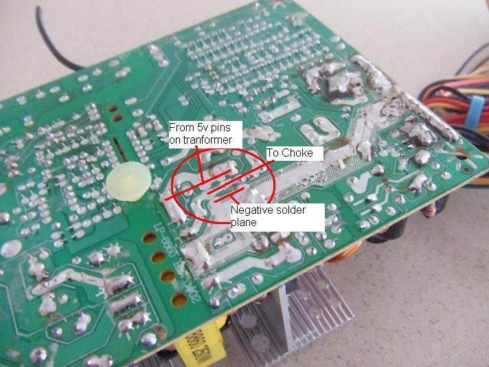
(BTW, all that terrible soldering is from the factory )
)
On the 5v, there is a 30A, 40V schottky. One of the outside legs is connected to the 5v output of the transformer. The other outside leg just goes to negative. This is true for both the schottky's on the 5v (silkscreened for two,) I recall the leadman lp-8860 based Real PC power in the JG bargain basement roundup had two of these 30A, 40V schottky's on the 5v, with the opposite leg cut off of each. So one would have one connected to the 5v pins on the transformer, the other had one that just went to negative.
Pic:
(BTW, all that terrible soldering is from the factory
Attached Files
if you find these attachements useful please consider making a small donation to the site


Comment