PSU Recapping time! 
This is the same HiPro model HP-P3017F3 PSU detailed here . Only created this thread to make the information easier to find… and to show the slightly different capacitors used in this second PSU.
https://www.badcaps.net/forum/attach...1&d=1578889373
https://www.badcaps.net/forum/attach...1&d=1578889373
https://www.badcaps.net/forum/attach...1&d=1578889373
https://www.badcaps.net/forum/attach...1&d=1578889373
https://www.badcaps.net/forum/attach...1&d=1578889373
https://www.badcaps.net/forum/attach...1&d=1578889373
https://www.badcaps.net/forum/attach...1&d=1578889373
And the daughterboard showing the Weltrend WT7525 controller IC;
https://www.badcaps.net/forum/attach...1&d=1578889373
https://www.badcaps.net/forum/attach...1&d=1578889373
Cap diagram of what rail each cap is connected to on the output side.
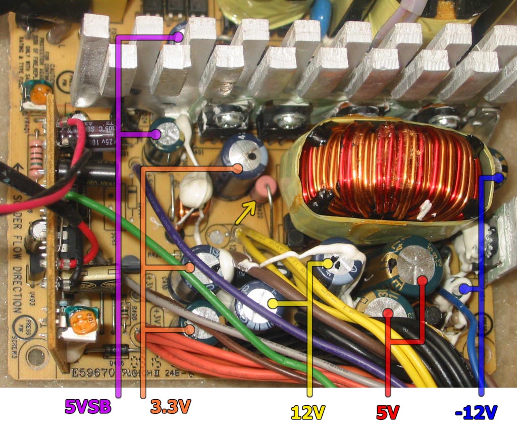
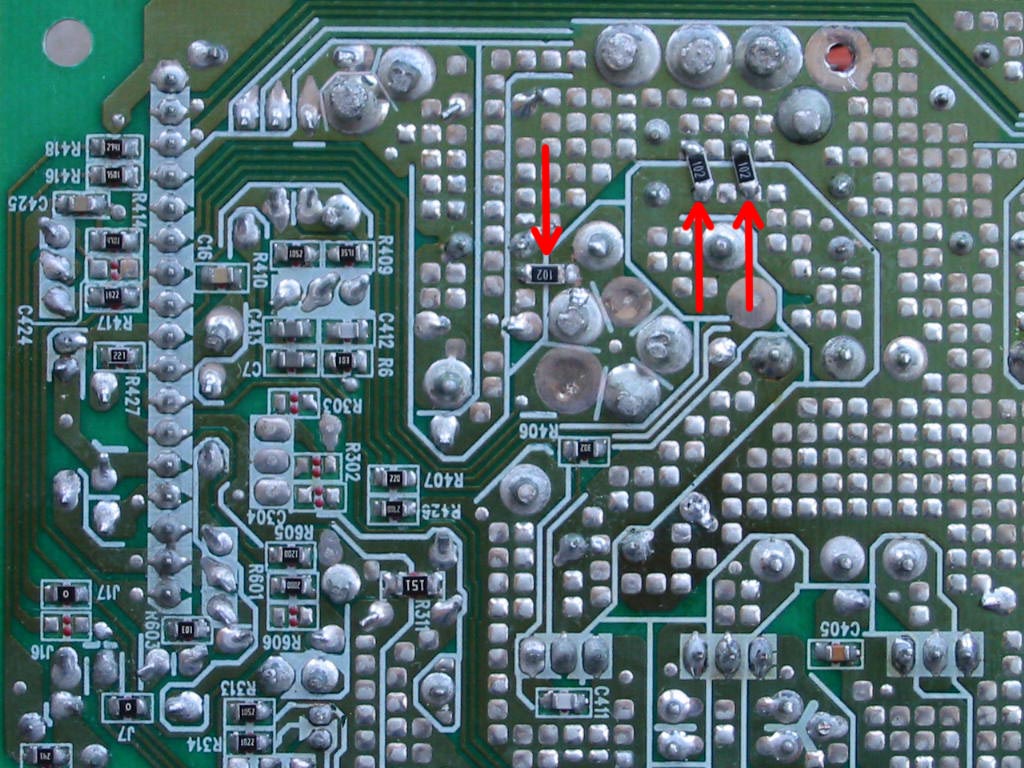
Everything should be self-explanatory on that picture. Only thing I need to note is the yellow arrow, which points to resistor R422. This resistor is installed as a minimum load on the 12V rail, but isn’t really needed if the PSU will be used on a 12-based PC. I usually remove it and replace it with a higher value one (anything ~250 Ohms or more is a good idea.) Reason why is because it is rated 75 Ohms and 3 Watts. Being connected on the 12V rail, this means it dissipates close to 2 Watts of heat – enough to darken the PCB over time and expedite the demise of the nearby output caps (especially the one right next to it for the 3.3V rail.) For the PSU above, I removed R422 and installed three (3) 1-KOhm 1/4W SMD resistors on the bottom of the PCB between the 12V rail and ground (the parallel equivalent of one 333-Ohm resistor, which @ 12V will dissipate less than ½ Watt of heat.) You can see them annotated here with the red arrows:
And finally, here is how I recapped my unit:
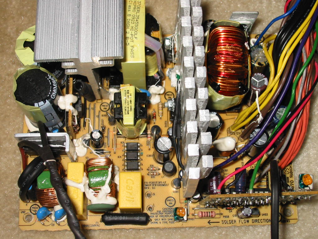
It’s not quite a full recap (due to always being short on caps in my inventory), but most of the important caps have been replaced.
This is what the PSU has on the outputs, in terms of caps:
* 5VSB
*** 1x Ltec LZP, 10V, 2200 uF, 10x20 mm before PI coil
*** 1x Teapo SC, 10V, 470 uF, 8x13 mm after PI coil (note: space for this cap has 5 mm lead spacing and can accommodate a 10 mm diameter cap, if needed)
* 3.3V Rail
*** 1x Ltec LZP, 10V, 2200 uF, 10x20 mm before linear regulator
*** 1x Ltec LZP, 10V, 2200 uF, 10x20 mm after linear regulator
*** 1x Teapo SC, 10V, 1000 uF, 10x15 mm after linear regulator
* 5V Rail
*** 2x Teapo SC, 10V, 4700 uF, 12.5x25 mm with PI coil in between
* 12V Rail
*** 2x Ltec LZP, 16V, 2200 uF, 10x30 mm
* -12V Rail
*** 1x Teapo SC, 35V, 470 uF, 10x20 mm before 7912 linear regulator
*** 1x Ltec LZP, 16V/25V, 100 uF (?), 5x11 mm after 7912 linear
.
.
And here is what I recapped on this power supply:
* 5VSB
*** 1x Ltec LZP, 10V, 2200 uF, 10x20 mm ---> Nichicon HN, 16V, 1500 uF, 10x20 mm
* 3.3V Rail
*** 2x Ltec LZP, 10V, 2200 uF, 10x20 mm ---> Rubycon ZLH, 6.3V, 2200 uF, 10x20 mm
* 5V Rail
*** no change (left the big 4700 uF Teapo SC caps alone, as they measured good.)
* 12V Rail
*** 1x Ltec LZP, 10V, 2200 uF, 10x20 mm ---> United Chemicon KYB, 16V, 2200 uF
* -12V Rail
*** 1x Ltec LZP, 16V or 25V, 100 uF (?), 5x11 ---> Rubycon YXJ, 25V, 220 uF, 6.3x12
I also replaced many of the small caps related to the control circuits. Here is an almost complete list of these small caps:
2x Teapo SEK, 25V, 100 uF, 6.3x11 mm
3x Ltec TK, 50V, 2.2 uF, 5x11 mm
1x Ltec TK, 16V, 47 uF, 5x11 mm
There are three more small caps, but I could not identify/read their values.
But really, replacing the output filter caps and the small caps listed above should pretty much make this PSU bullet-proof. I use PSUs like this all the time in my basic builds, so they always come in handy to have.
This is the same HiPro model HP-P3017F3 PSU detailed here . Only created this thread to make the information easier to find… and to show the slightly different capacitors used in this second PSU.
https://www.badcaps.net/forum/attach...1&d=1578889373
https://www.badcaps.net/forum/attach...1&d=1578889373
https://www.badcaps.net/forum/attach...1&d=1578889373
https://www.badcaps.net/forum/attach...1&d=1578889373
https://www.badcaps.net/forum/attach...1&d=1578889373
https://www.badcaps.net/forum/attach...1&d=1578889373
https://www.badcaps.net/forum/attach...1&d=1578889373
And the daughterboard showing the Weltrend WT7525 controller IC;
https://www.badcaps.net/forum/attach...1&d=1578889373
https://www.badcaps.net/forum/attach...1&d=1578889373
Cap diagram of what rail each cap is connected to on the output side.
Everything should be self-explanatory on that picture. Only thing I need to note is the yellow arrow, which points to resistor R422. This resistor is installed as a minimum load on the 12V rail, but isn’t really needed if the PSU will be used on a 12-based PC. I usually remove it and replace it with a higher value one (anything ~250 Ohms or more is a good idea.) Reason why is because it is rated 75 Ohms and 3 Watts. Being connected on the 12V rail, this means it dissipates close to 2 Watts of heat – enough to darken the PCB over time and expedite the demise of the nearby output caps (especially the one right next to it for the 3.3V rail.) For the PSU above, I removed R422 and installed three (3) 1-KOhm 1/4W SMD resistors on the bottom of the PCB between the 12V rail and ground (the parallel equivalent of one 333-Ohm resistor, which @ 12V will dissipate less than ½ Watt of heat.) You can see them annotated here with the red arrows:
And finally, here is how I recapped my unit:
It’s not quite a full recap (due to always being short on caps in my inventory), but most of the important caps have been replaced.
This is what the PSU has on the outputs, in terms of caps:
* 5VSB
*** 1x Ltec LZP, 10V, 2200 uF, 10x20 mm before PI coil
*** 1x Teapo SC, 10V, 470 uF, 8x13 mm after PI coil (note: space for this cap has 5 mm lead spacing and can accommodate a 10 mm diameter cap, if needed)
* 3.3V Rail
*** 1x Ltec LZP, 10V, 2200 uF, 10x20 mm before linear regulator
*** 1x Ltec LZP, 10V, 2200 uF, 10x20 mm after linear regulator
*** 1x Teapo SC, 10V, 1000 uF, 10x15 mm after linear regulator
* 5V Rail
*** 2x Teapo SC, 10V, 4700 uF, 12.5x25 mm with PI coil in between
* 12V Rail
*** 2x Ltec LZP, 16V, 2200 uF, 10x30 mm
* -12V Rail
*** 1x Teapo SC, 35V, 470 uF, 10x20 mm before 7912 linear regulator
*** 1x Ltec LZP, 16V/25V, 100 uF (?), 5x11 mm after 7912 linear
.
.
And here is what I recapped on this power supply:
* 5VSB
*** 1x Ltec LZP, 10V, 2200 uF, 10x20 mm ---> Nichicon HN, 16V, 1500 uF, 10x20 mm
* 3.3V Rail
*** 2x Ltec LZP, 10V, 2200 uF, 10x20 mm ---> Rubycon ZLH, 6.3V, 2200 uF, 10x20 mm
* 5V Rail
*** no change (left the big 4700 uF Teapo SC caps alone, as they measured good.)
* 12V Rail
*** 1x Ltec LZP, 10V, 2200 uF, 10x20 mm ---> United Chemicon KYB, 16V, 2200 uF
* -12V Rail
*** 1x Ltec LZP, 16V or 25V, 100 uF (?), 5x11 ---> Rubycon YXJ, 25V, 220 uF, 6.3x12
I also replaced many of the small caps related to the control circuits. Here is an almost complete list of these small caps:
2x Teapo SEK, 25V, 100 uF, 6.3x11 mm
3x Ltec TK, 50V, 2.2 uF, 5x11 mm
1x Ltec TK, 16V, 47 uF, 5x11 mm
There are three more small caps, but I could not identify/read their values.
But really, replacing the output filter caps and the small caps listed above should pretty much make this PSU bullet-proof. I use PSUs like this all the time in my basic builds, so they always come in handy to have.
Attached Files
if you find these attachements useful please consider making a small donation to the site


 Being that it will filter the 3.3V rail (which is linearly regulated and has very low ripple output), I don't see it getting stressed much. And it's also for an experiment to see how much longer it will last.


Comment