Trying to repair a MPI5.5kW solar inverter

Collapse
X
 
  • Time
  • Show
Clear All
new posts
  • Francesc V.
    Tempus fugit
    • Nov 2022
    • 221
    • Catalonia

    #1

    Trying to repair a MPI5.5kW solar inverter

    My parent's solar inverter died after 5 years of good service.

    It's a called hybrid inverter:
    - It can go with or without batteries
    - It has 2 MPPT (8 330W panels in 2 strings) -> 5280Wp
    - A 20kWh lithium battery previously used in a Nissan leaf (14S at 4.1V max) -> 57.4V

    Panel is showing error 17 and the battery connection has disappeared. On the other hand, is delivering load, MPPTs are working and it's exporting energy to the GRID. Not that "bad".

    Let's open it......
    I see that 150A fuse is gone and the DC input is shorted.

    This is the summary I've seen when I removed the PCB from the cabinet:


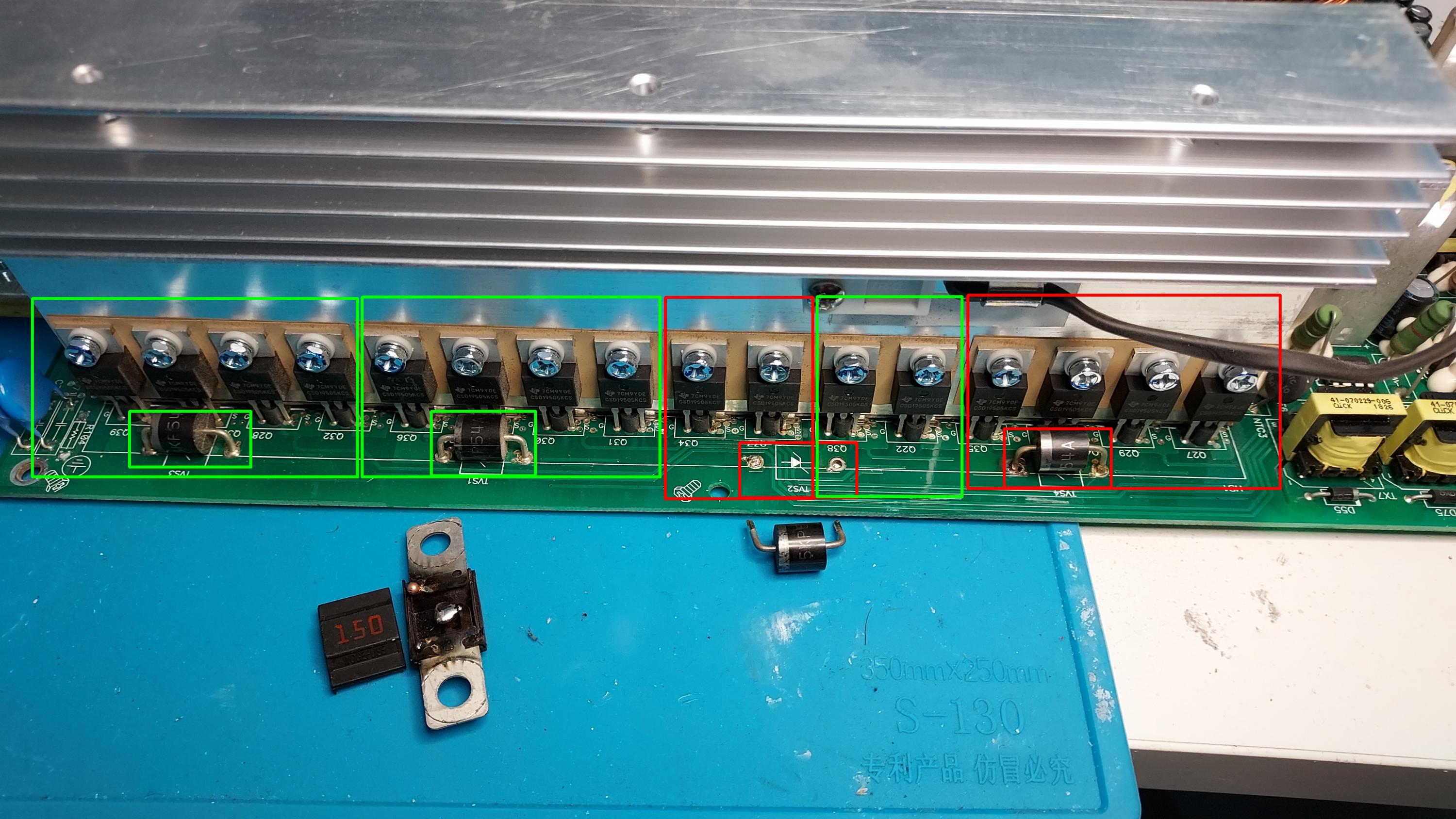
    Red is bad.......green is OK

    1st question: Is it ok to just change the 8 mosfets from the right as long as they go in groups of 4? Otherwise this repair will cost quite a lot :-)

    As soon as I've removed the TVS(4) and all the mosfets input shortcircuit has been removed............. but there are other possible shorts......which maybe are "ok".
    I am trying to understand the short on D16........but I haven't found it yet........maybe there is a reason behind it.

    Regards,
    Francesc.
    Attached Files
    Last edited by Francesc V.; 03-07-2023, 06:26 AM.
  • CapLeaker
    Leaking Member
    • Dec 2014
    • 8000
    • Canada

    #2
    Re: Trying to repair a MPI5.5kW solar inverter

    The 5KP54A TVS diode is unidirectional and fires off at 54V reverse standoff in order to protect the circuitry by usually shorting a protecting voltage rail to gnd and blow a fuse. So it does make sense what you found.

    So you found a blown fuse, a shorted protection diode and shorted mosfets. Now look if the mosfet is shorted to the gate pin, if it is, check the gate drive circuit of the mosfet too.

    If you can find original mosfets, I’d change them out in banks (2 right banks). Now if you have to sub something else into it, I’d be changing them all.

    Got no idea what D16 is, but it is rectifying voltage from the transformer.
    Last edited by CapLeaker; 03-08-2023, 06:02 AM.

    Comment

    • Francesc V.
      Tempus fugit
      • Nov 2022
      • 221
      • Catalonia

      #3
      Re: Trying to repair a MPI5.5kW solar inverter

      Thanks for you're valuable input.

      The mosfet part.........including the drivers (npn & pnp) and resistors look perfect, so I leave it pending to receive the new mosfets.

      In the meantime I am trying to "understand" D16. If I remove the transformer the short is gone and the diode reads ok..... so it's something like this right?


      And this means that something is still wrong in that circuit......right? I could try to inject voltage there.........what do you think?

      Regards,
      Francesc.

      P.S: I've ordered a new PCB.......I need to be a good son and not loose my parent's patience
      Attached Files

      Comment

      • CapLeaker
        Leaking Member
        • Dec 2014
        • 8000
        • Canada

        #4
        Re: Trying to repair a MPI5.5kW solar inverter

        This is o.k… it’s just a simple half bridge rectifier. Just a small mistake in your drawing, since you shorted negative and positive together after the cap. You didn’t put a load there.
        Just fix the TVS, the mosfets, the fuse and check the parts in the gate drive to the mosfets. Hopefully that’s all that’s wrong with it.

        Comment

        • Francesc V.
          Tempus fugit
          • Nov 2022
          • 221
          • Catalonia

          #5
          Re: Trying to repair a MPI5.5kW solar inverter

          Originally posted by CapLeaker
          This is o.k… it's just a simple half bridge rectifier. Just a small mistake in your drawing, since you shorted negative and positive together after the cap. You didn't put a load there.
          Just fix the TVS, the mosfets, the fuse and check the parts in the gate drive to the mosfets. Hopefully that's all that's wrong with it.
          You're absolutely right. New PCB has arrived (it took only 5 days from Taiwan) and it has the same behaviour (D16 "shorted").

          So, I will wait for the ordered material and fix this one to have it for emergency cases.

          I leave an schematic for the drive part.......just if someone needs it (I found it and it's very usefull).

          Regards,
          Francesc.
          Attached Files

          Comment

          • Jacupp
            New Member
            • Jul 2023
            • 2
            • United Kingdom

            #6
            Re: Trying to repair a MPI5.5kW solar inverter

            Hi Francesc, how did You get on with fixing the inverter? I have MPI5.5KW and it suddenly stopped "seeing" the panels. When I checked a string before connecting it to inverter it was definitely showing voltage of about 250 and they were giving off significant (around 10A) of shrot circuit current on cloudy day. After connecting to inverter and switching panel switch to ON position the voltage "disappeared" - showed 0. Am I correct to think that there must be a dead short to the ground somewhere? I am basing this dead short to ground hypothesis on the fact that there was no obvious magic smoke coming out of anywhere. On or around inverter, cabling, fuses, switches etc.

            Comment

            • Francesc V.
              Tempus fugit
              • Nov 2022
              • 221
              • Catalonia

              #7
              Re: Trying to repair a MPI5.5kW solar inverter

              Originally posted by Jacupp
              Hi Francesc, how did You get on with fixing the inverter? I have MPI5.5KW and it suddenly stopped "seeing" the panels. When I checked a string before connecting it to inverter it was definitely showing voltage of about 250 and they were giving off significant (around 10A) of shrot circuit current on cloudy day. After connecting to inverter and switching panel switch to ON position the voltage "disappeared" - showed 0. Am I correct to think that there must be a dead short to the ground somewhere? I am basing this dead short to ground hypothesis on the fact that there was no obvious magic smoke coming out of anywhere. On or around inverter, cabling, fuses, switches etc.
              Hi Jacupp:

              In your case, the DC-DC PCB is the one that is broken. If not able to repair, Mppsolar can sell you the whole PCB.

              Good luck with it.
              Francesc.

              Comment

              • Jacupp
                New Member
                • Jul 2023
                • 2
                • United Kingdom

                #8
                Hi Francesco, would You be able to help and point me in the right direction with regards to trying to repair the DC-DC PCB? And most importantly how would I establish what caused the damage to the PCB in the first place?
                If I could repair it myself it would be great way to save around GBP180. Thanks For Your help.
                Jakub

                Comment

                Related Topics

                Collapse

                • mitsu2k
                  Power-One solar Inverter driving me NUTS!!!
                  by mitsu2k
                  Hello folks, this is a last ditch effort. I thought I would seek your expertise before giving up.. I have been working on this thing for over 2 months and have gotten nowhere. Here is the issue:
                  Inverter powers on and immediately red GFI light comes on and inverter will not complete the initialization process.
                  There is no error code on the screen. I have removed most of the Y capacitors and tested to no avail.
                  All relays are good.
                  I replaced the current transducer- same problem. Checked most of the transistors and diodes and all appear good. I wish I could get my hands...
                  11-13-2023, 07:19 PM
                • BlackScreen_22
                  Harman Kardon sub TS11 (ds15 amplifer) blows fuse and mosfets
                  by BlackScreen_22
                  Hi, I'll start by saying that I'm not an expert and I've reached a point where I don't know what to try/do anymore...
                  Starting from the beginning: I opened this subwoofer for the first time with a very strong smell of burnt electrical components, I realize that on the amplifier board there is a hole between V+ OUT and GND about the size of a finger, the damaged components were the shorted mosfets, two damaged zener diodes and two capacitors. I bought everything, I fixed the hole by cutting the pcb and putting a piece of a perforated board.
                  I had no problems connecting mosfets and capacitors,...
                  08-27-2024, 12:46 PM
                • kotel studios
                  Intel D865PERL - no Vcore after replacing MOSFETs and MOSFET drivers
                  by kotel studios
                  Hi,

                  Finally got time to fix this board up.
                  At first it didn't give any POST codes. Turns out it was an unsupported Celeron D cpu. After dropping in an Celery 2.6gHz the CPU came out of reset with clock signal, but still no post codes. For a while it did work when I applied pressure to the ADP3168 chip, but on next reboot the MOSFETs started to burn. Then I left it as is for months.

                  Now I came back prepared. Replaced the bad MOSFETs and the ADPxx18k drivers. Now I don't get any MOSFETs blowing up issues anymore. But sadly, the Vcore is missing. The whole VRM isn't...
                  04-22-2025, 05:08 AM
                • x_orange90_x
                  Vizio E55-E1 bad backlights or bad inverter?
                  by x_orange90_x
                  I just got this tv today and it appeared to have no backlight on. After taking off the rear cover and checking again in the dark I can see that MAYBE one quadrant is lit.. But still it's quite dim. I was going to check the LEDs with my tester, and I found LED 1 and LED 2 + pins on the wire from the inverter, but I couldn't identify a ground. Nonetheless I tried using a mounting screw on the inverter board and also the chassis as ground but regardless my tester reads 300 which is what it reads when there is no voltage draw.

                  I don't know how exactly to test the inverter itself. Is it...
                  01-29-2025, 09:24 PM
                • flerre
                  Gainward Phantom GTX 980 - mosfets w/ integrated driver NCP5369
                  by flerre
                  Hi!

                  Managed to get a Gainward Phantom GTX 980 in an auction for a bin with components.
                  No video out so I started fault finding and found a blown fuse for 3 mosfets. Started checking for shorts and found what I think is a short through all of those 3 mosfets; 0.1 ohms between "VIN" input and "VSWH" output. All mosfets in this gpu are the same ones (NCP5369) with integrated drivers and when I tried measuring the other ones through these ports they were somewhere in the kilo-ohms range.

                  So, could I safely assume all of these 3 mosfets are...
                  03-13-2022, 12:14 PM
                • Loading...
                • No more items.
                Working...