Anyone Have experience/Schematic w/ Acer Aspire 5532 Motherboard?

Collapse
X
 
  • Time
  • Show
Clear All
new posts
  • Paul678
    Badcaps Veteran
    • Nov 2011
    • 402

    #1

    Anyone Have experience/Schematic w/ Acer Aspire 5532 Motherboard?

    I just want to know before I post some pics.

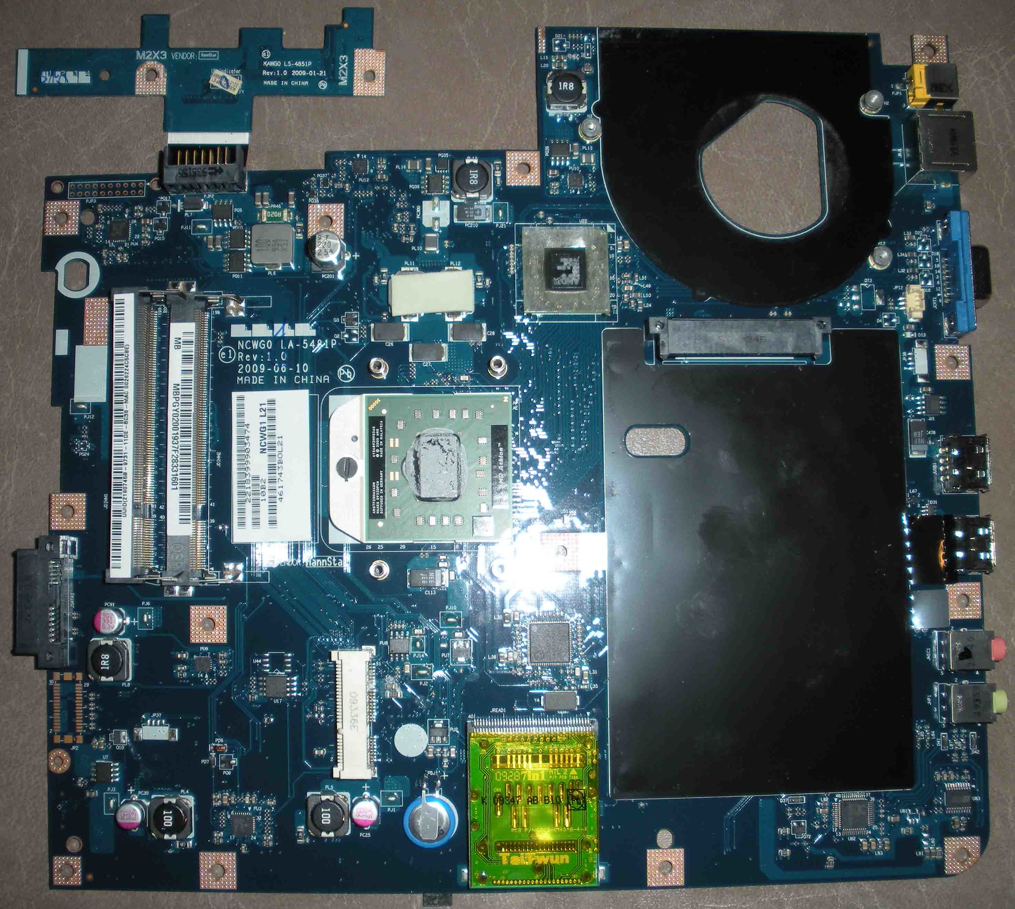
    The board simply does not turn on at all. The 19Volts
    is healthy at the input, so there is no short to ground,
    but still nothing.

    I looked for voltages on the ribbon going to the power
    switch board, and there is nothing.

    Someone had apparently spilled some sort of
    fluid on this one. I got off most of the gunk with
    alcohol, but it still does nothing.

    I know it's a long shot, but I just wanted to see
    if someone had an idea of which components I should
    look at first.....

    Thanks for reading
  • Paul678
    Badcaps Veteran
    • Nov 2011
    • 402

    #2
    Re: Anyone Have experience/Schematic w/ Acer Aspire 5532 Motherboard?

    Ok, here are some pics big enough to see component
    markers:


    I was able to trace the +19V to the 3.3 Ohm resistors,
    PR43 and PR40 (to the right edge of large fan opening),
    but it appeared to stop at that point.

    Again, there were no significant voltages on the ribbon
    going to the power/On-Off board, just some 0.4 Volts
    here and there, and again, nothing happens when I
    press the ON button.

    I know it's a long shot, but if someone has any ideas of
    where to look next, it would be much appreciated.

    Comment

    • severach
      Badcaps Legend
      • Aug 2007
      • 1055
      • USA

      #3
      Re: Anyone Have experience/Schematic w/ Acer Aspire 5532 Motherboard?

      Measure voltage at the on/off button. One of the pins will change from 3.3v to 0v when the power button is pushed.
      sig files are for morons

      Comment

      • Paul678
        Badcaps Veteran
        • Nov 2011
        • 402

        #4
        Re: Anyone Have experience/Schematic w/ Acer Aspire 5532 Motherboard?

        Originally posted by severach
        Measure voltage at the on/off button. One of the pins will change from 3.3v to 0v when the power button is pushed.
        There was one pin on at the on/off button that
        measured about 0.3 V, so that's probably what
        should be +3.3V. I traced it to the motherboard,
        but I couldn't find what components it leads to.

        Needle in Haystack without a schematic.....

        Comment

        • nucleus
          Senior Member
          • May 2012
          • 64
          • Montenegro

          #5
          Re: Anyone Have experience/Schematic w/ Acer Aspire 5532 Motherboard?

          here is link for schematics.

          http://lqv77.com/download/648/

          Comment

          • Paul678
            Badcaps Veteran
            • Nov 2011
            • 402

            #6
            Re: Anyone Have experience/Schematic w/ Acer Aspire 5532 Motherboard?

            Originally posted by nucleus
            here is link for schematics.

            http://lqv77.com/download/648/

            Thanks, that's a huge help, even though it doesn't
            exactly match my board, component ID wise, which
            shouldn't surprise any of the engineers out there.

            But I was missing the +3VALW, which is +3.3V always
            on, which is what the on/off switch shorts to ground.

            According to the schematic, it's generated by this:


            So I found this IC on my board, and it indeed was
            attached to the switch, but it was missing the reference
            voltage, which ranges from +5.5 to +25V.

            It should have been safe to jumper the +19V
            input voltage to this chip, but when I tried it,
            the IC started smoking! Damn! The chip
            is supposed to be always on!

            Oh well, I'm gonna end up parting this laptop
            out.....the LCD screen display and housing
            is gonna fetch $80 alone!

            Thanks for the input anyways.....Remember that
            research and curiosity are NEVER in vain!

            Comment

            • nucleus
              Senior Member
              • May 2012
              • 64
              • Montenegro

              #7
              Re: Anyone Have experience/Schematic w/ Acer Aspire 5532 Motherboard?

              try to replace chip first if you have it on some old board. also chek on schematics which are pins for input voltages and if there is volatge that should be. if there is no input V trace it to where it should come from.

              Comment

              • Paul678
                Badcaps Veteran
                • Nov 2011
                • 402

                #8
                Re: Anyone Have experience/Schematic w/ Acer Aspire 5532 Motherboard?

                Originally posted by nucleus
                try to replace chip first if you have it on some old board. also chek on schematics which are pins for input voltages and if there is volatge that should be. if there is no input V trace it to where it should come from.

                I don't have a hot-air rework station. And I only have one
                other old board, and it doesn't have the same chip.

                According to the schematic, the input voltage should come
                from either the battery or the AC adaptor's +19V, which
                makes sense because it's outputting the "always on" voltages.

                Comment

                • mattbrad2
                  Senior Member
                  • Jan 2011
                  • 122

                  #9
                  Re: Anyone Have experience/Schematic w/ Acer Aspire 5532 Motherboard?

                  Paul, the problem all along was the intersil PWM IC. A common problem in this series of Acer. Replace that and you *would* have been fine however now there may be more damage.

                  Comment

                  • Paul678
                    Badcaps Veteran
                    • Nov 2011
                    • 402

                    #10
                    Re: Anyone Have experience/Schematic w/ Acer Aspire 5532 Motherboard?

                    Originally posted by mattbrad2
                    Paul, the problem all along was the intersil PWM IC. A common problem in this series of Acer. Replace that and you *would* have been fine however now there may be more damage.

                    Oh no, another "know-it-all" personality, who doesn't know
                    what he's talking about!

                    This had nothing to do with pulse width modulation. Look
                    at the schematic, and there are "always on" voltages. Both the
                    +3.3V and the +5V always on weren't there, so the computer
                    could not be turned on.

                    Comment

                    • tom66
                      EVs Rule
                      • Apr 2011
                      • 32560
                      • UK

                      #11
                      Re: Anyone Have experience/Schematic w/ Acer Aspire 5532 Motherboard?

                      PWM often drives a buck converter to generate 3.3V and 5V supplies... (so called always on supplies.)
                      Please do not PM me with questions! Questions via PM will not be answered. Post on the forums instead!
                      For service manual, schematic, boardview (board view), datasheet, cad - use our search.

                      Comment

                      • Paul678
                        Badcaps Veteran
                        • Nov 2011
                        • 402

                        #12
                        Re: Anyone Have experience/Schematic w/ Acer Aspire 5532 Motherboard?

                        Originally posted by tom66
                        PWM often drives a buck converter to generate 3.3V and 5V supplies... (so called always on supplies.)
                        The datasheet says it's a linear regulator for the
                        fixed +3.3 and +5Volts:


                        If this chip is for the "always on" voltages, why wasn't the
                        +19V at the Vin?

                        Perhaps because the chip itself had Vin shorted
                        to ground, and burned out the trace.

                        Comment

                        • tom66
                          EVs Rule
                          • Apr 2011
                          • 32560
                          • UK

                          #13
                          Re: Anyone Have experience/Schematic w/ Acer Aspire 5532 Motherboard?

                          No idea - there's a reason I don't work on laptops often.
                          Please do not PM me with questions! Questions via PM will not be answered. Post on the forums instead!
                          For service manual, schematic, boardview (board view), datasheet, cad - use our search.

                          Comment

                          • mattbrad2
                            Senior Member
                            • Jan 2011
                            • 122

                            #14
                            Re: Anyone Have experience/Schematic w/ Acer Aspire 5532 Motherboard?

                            Originally posted by Paul678
                            Oh no, another "know-it-all" personality, who doesn't know
                            what he's talking about!

                            This had nothing to do with pulse width modulation. Look
                            at the schematic, and there are "always on" voltages. Both the
                            +3.3V and the +5V always on weren't there, so the computer
                            could not be turned on.
                            Not quite sure where the attitude is coming from but I'll be sure not to help you out in the future. All I was saying was I've seen this exact problem on this exact series (I've been working on laptops for 20 years) and its always been that intersil IC. It's this IC that is generating your "always on" voltage. Both 5v AND 3.3 come from this little guy. I'm not sure how you're reading that schematic but its pretty clear to me. Anyway.. I won't respond to this thread any longer. Good luck.
                            Last edited by mattbrad2; 05-22-2012, 09:29 PM.

                            Comment

                            • budm
                              Badcaps Legend
                              • Feb 2010
                              • 40746
                              • USA

                              #15
                              Re: Anyone Have experience/Schematic w/ Acer Aspire 5532 Motherboard?

                              "The datasheet says it's a linear regulator for the
                              fixed +3.3 and +5Volts:


                              From the Data sheet you provided: page1
                              "The ISL6237 dual step-down, switch-mode power-supply
                              (SMPS) controller generates logic-supply voltages in
                              battery-powered systems. The ISL6237 includes two
                              pulse-width modulation (PWM) controllers, 5V/3.3V and
                              1.5V/1.05V. The output of SMPS1 can also be adjusted from
                              0.7V to 5.5V. The SMPS2 output can be adjusted from 0.5V to
                              2.5V by setting REFIN2 voltage. This device features a linear
                              regulator providing 3.3V/5V, or adjustable from 0.7V to 4.5V
                              output via LDOREFIN. The linear regulator provides up to
                              100mA output current with automatic linear-regulator
                              bootstrapping to the BYP input. When in switchover, the LDO
                              output can source up to 200mA. The ISL6237 includes
                              on-board power-up sequencing, power-good (POK_) outputs,
                              digital soft-start, and internal soft-stop output discharge that
                              prevents negative voltages on shutdown.
                              Constant on-time PWM control scheme operates without
                              sense resistors and provides 100ns response to load
                              transients while maintaining a relatively constant switching
                              frequency. The unique ultrasonic pulse-skipping mode
                              maintains the switching frequency above 25kHz, which
                              eliminates noise in audio applications. Other features include
                              pulse skipping, which maximizes efficiency in light-load
                              applications, and fixed-frequency PWM mode, which reduces
                              RF interference in sensitive applications."
                              Never stop learning
                              Basic LCD TV and Monitor troubleshooting guides.
                              http://www.badcaps.net/forum/showthr...956#post305956

                              Voltage Regulator (LDO) testing:
                              http://www.badcaps.net/forum/showthr...999#post300999

                              Inverter testing using old CFL:
                              http://www.badcaps.net/forum/showthr...er+testing+cfl

                              Tear down pictures : Hit the ">" Show Albums and stories" on the left side
                              http://s807.photobucket.com/user/budm/library/

                              TV Factory reset codes listing:
                              http://www.badcaps.net/forum/showthread.php?t=24809

                              Comment

                              • Paul678
                                Badcaps Veteran
                                • Nov 2011
                                • 402

                                #16
                                Re: Anyone Have experience/Schematic w/ Acer Aspire 5532 Motherboard?

                                Originally posted by mattbrad2
                                Not quite sure where the attitude is coming from but I'll be sure not to help you out in the future. All I was saying was I've seen this exact problem on this exact series (I've been working on laptops for 20 years) and its always been that intersil IC. It's this IC that is generating your "always on" voltage. Both 5v AND 3.3 come from this little guy. I'm not sure how you're reading that schematic but its pretty clear to me. Anyway.. I won't respond to this thread any longer. Good luck.

                                Thanks for repeating what I just posted earlier!

                                Did you even read the schematic?

                                Page 5 and 33 show how this chip supplies
                                the +3.3V to the power switch.

                                And you are wrong about replacing the chip
                                and I would have been fine, because the +19V
                                wasn't even present. It should always be present,
                                if this chip is "always on". So at the least, I would
                                have had to install a jumper to the +19V. If anything,
                                the trace may have acted as a fuse, and prevented
                                the IC from smoking the way it did when I jumpered
                                it, but the chip was certainly bad.
                                Last edited by Paul678; 05-23-2012, 04:58 AM.

                                Comment

                                • Paul678
                                  Badcaps Veteran
                                  • Nov 2011
                                  • 402

                                  #17
                                  Re: Anyone Have experience/Schematic w/ Acer Aspire 5532 Motherboard?

                                  Originally posted by budm
                                  "The datasheet says it's a linear regulator for the
                                  fixed +3.3 and +5Volts:


                                  From the Data sheet you provided: page1
                                  "The ISL6237 dual step-down, switch-mode power-supply
                                  (SMPS) controller generates logic-supply voltages in
                                  battery-powered systems. The ISL6237 includes two
                                  pulse-width modulation (PWM) controllers, 5V/3.3V and
                                  1.5V/1.05V. The output of SMPS1 can also be adjusted from
                                  0.7V to 5.5V. The SMPS2 output can be adjusted from 0.5V to
                                  2.5V by setting REFIN2 voltage. This device features a linear
                                  regulator providing 3.3V/5V, or adjustable from 0.7V to 4.5V
                                  output via LDOREFIN. The linear regulator provides up to
                                  100mA output current with automatic linear-regulator
                                  bootstrapping to the BYP input. When in switchover, the LDO
                                  output can source up to 200mA. The ISL6237 includes
                                  on-board power-up sequencing, power-good (POK_) outputs,
                                  digital soft-start, and internal soft-stop output discharge that
                                  prevents negative voltages on shutdown.
                                  Constant on-time PWM control scheme operates without
                                  sense resistors and provides 100ns response to load
                                  transients while maintaining a relatively constant switching
                                  frequency. The unique ultrasonic pulse-skipping mode
                                  maintains the switching frequency above 25kHz, which
                                  eliminates noise in audio applications. Other features include
                                  pulse skipping, which maximizes efficiency in light-load
                                  applications, and fixed-frequency PWM mode, which reduces
                                  RF interference in sensitive applications."
                                  From your quote:

                                  "This device features a linear
                                  regulator providing 3.3V/5V, or adjustable from 0.7V to 4.5V
                                  output via LDOREFIN. The linear regulator provides up to
                                  100mA output current with automatic linear-regulator
                                  bootstrapping to the BYP input. "

                                  Comment

                                  • budm
                                    Badcaps Legend
                                    • Feb 2010
                                    • 40746
                                    • USA

                                    #18
                                    Re: Anyone Have experience/Schematic w/ Acer Aspire 5532 Motherboard?

                                    There is only ONE LDO output with very limited current output, it can be set to output 5V or 3.3V.
                                    See page 23 for typical setup for TWO output supplies 3.3V AND 5V for always on power supply.
                                    So look at the board and see if the IC is hooked close to as shown in the app notes.
                                    Attached Files
                                    Never stop learning
                                    Basic LCD TV and Monitor troubleshooting guides.
                                    http://www.badcaps.net/forum/showthr...956#post305956

                                    Voltage Regulator (LDO) testing:
                                    http://www.badcaps.net/forum/showthr...999#post300999

                                    Inverter testing using old CFL:
                                    http://www.badcaps.net/forum/showthr...er+testing+cfl

                                    Tear down pictures : Hit the ">" Show Albums and stories" on the left side
                                    http://s807.photobucket.com/user/budm/library/

                                    TV Factory reset codes listing:
                                    http://www.badcaps.net/forum/showthread.php?t=24809

                                    Comment

                                    • Paul678
                                      Badcaps Veteran
                                      • Nov 2011
                                      • 402

                                      #19
                                      Re: Anyone Have experience/Schematic w/ Acer Aspire 5532 Motherboard?

                                      Originally posted by mattbrad2
                                      Paul, the problem all along was the intersil PWM IC. A common problem in this series of Acer. Replace that and you *would* have been fine however now there may be more damage.
                                      You are incorrect.

                                      It turns out there is no B+ anywhere on this board, so this chip was
                                      NOT the problem.

                                      There's a good reason I don't trust people who say they
                                      are 100% sure they know the problem.....

                                      Nevertheless, thanks to Nucleus for the excellent schematic!

                                      Do you really live in this tiny little town?

                                      http://en.wikipedia.org/wiki/Bijelo_Polje
                                      Last edited by Paul678; 05-24-2012, 05:34 AM.

                                      Comment

                                      • budm
                                        Badcaps Legend
                                        • Feb 2010
                                        • 40746
                                        • USA

                                        #20
                                        Re: Anyone Have experience/Schematic w/ Acer Aspire 5532 Motherboard?

                                        So on page 38 of the service manual where the ALWAYS ON 3.3V and 5V which are generated by the TWO SMPS you are not getting B+ at jumper PJ17?

                                        You also do not have VIN on page 38 from the DC input jack PJP1?

                                        Page 40: B+ comes from MOSFET switches PQ7, PQ8 which are turn on (PIN 4 ACDRV will go low when ACDET sees the VIN from AC adapter) when the ACDET PIN 5 of PU4 Power control IC sees VIN.
                                        Last edited by budm; 05-24-2012, 08:54 AM.
                                        Never stop learning
                                        Basic LCD TV and Monitor troubleshooting guides.
                                        http://www.badcaps.net/forum/showthr...956#post305956

                                        Voltage Regulator (LDO) testing:
                                        http://www.badcaps.net/forum/showthr...999#post300999

                                        Inverter testing using old CFL:
                                        http://www.badcaps.net/forum/showthr...er+testing+cfl

                                        Tear down pictures : Hit the ">" Show Albums and stories" on the left side
                                        http://s807.photobucket.com/user/budm/library/

                                        TV Factory reset codes listing:
                                        http://www.badcaps.net/forum/showthread.php?t=24809

                                        Comment

                                        Related Topics

                                        Collapse

                                        • Document Archive
                                          ACER Aspire Aspire E560 Aspire E6400 Specification for Upgrade or Repair
                                          by Document Archive
                                          This specification for the ACER Aspire Aspire E560 can be useful for upgrading or repairing a desktop PC that is not working. As a community we are working through our specifications to add valuable data like the Aspire Aspire E560 boardview and Aspire Aspire E560 schematic. Our users have donated over 1 million documents which are being added to the site. This page will be updated soon with additional information. Alternatively you can request additional help from our users directly on the relevant badcaps forum. Please note that we offer no warranties that any specification, datasheet, or download...
                                          09-12-2024, 03:28 PM
                                        • Document Archive
                                          ACER Aspire Aspire E700 Aspire E6300 Specification for Upgrade or Repair
                                          by Document Archive
                                          This specification for the ACER Aspire Aspire E700 can be useful for upgrading or repairing a desktop PC that is not working. As a community we are working through our specifications to add valuable data like the Aspire Aspire E700 boardview and Aspire Aspire E700 schematic. Our users have donated over 1 million documents which are being added to the site. This page will be updated soon with additional information. Alternatively you can request additional help from our users directly on the relevant badcaps forum. Please note that we offer no warranties that any specification, datasheet, or download...
                                          09-12-2024, 02:30 PM
                                        • Document Archive
                                          ACER Aspire Aspire M7711 Aspire Q9300 Specification for Upgrade or Repair
                                          by Document Archive
                                          This specification for the ACER Aspire Aspire M7711 can be useful for upgrading or repairing a desktop PC that is not working. As a community we are working through our specifications to add valuable data like the Aspire Aspire M7711 boardview and Aspire Aspire M7711 schematic. Our users have donated over 1 million documents which are being added to the site. This page will be updated soon with additional information. Alternatively you can request additional help from our users directly on the relevant badcaps forum. Please note that we offer no warranties that any specification, datasheet, or...
                                          09-12-2024, 03:28 PM
                                        • Document Archive
                                          ACER Aspire Aspire G7200 Predator Defender Aspire 9750 Specification for Upgrade or Repair
                                          by Document Archive
                                          This specification for the ACER Aspire Aspire G7200 Predator Defender can be useful for upgrading or repairing a desktop PC that is not working. As a community we are working through our specifications to add valuable data like the Aspire Aspire G7200 Predator Defender boardview and Aspire Aspire G7200 Predator Defender schematic. Our users have donated over 1 million documents which are being added to the site. This page will be updated soon with additional information. Alternatively you can request additional help from our users directly on the relevant badcaps forum. Please note that we offer...
                                          09-12-2024, 03:28 PM
                                        • Document Archive
                                          ACER Aspire Aspire M7200 Aspire 805 Specification for Upgrade or Repair
                                          by Document Archive
                                          This specification for the ACER Aspire Aspire M7200 can be useful for upgrading or repairing a desktop PC that is not working. As a community we are working through our specifications to add valuable data like the Aspire Aspire M7200 boardview and Aspire Aspire M7200 schematic. Our users have donated over 1 million documents which are being added to the site. This page will be updated soon with additional information. Alternatively you can request additional help from our users directly on the relevant badcaps forum. Please note that we offer no warranties that any specification, datasheet, or...
                                          09-12-2024, 03:28 PM
                                        • Loading...
                                        • No more items.
                                        Working...