Re: LED Resistor Calculations ...
Also, with everything powered up for over 10 minutes, the aluminum back plate is at 117 degrees C ... that's pretty damn hot! And at 12 volts, it's drawing 1.3 amps.
-
Re: Rim e: LED Resistor Calculations ...
So I just received the aluminum boards which are the same as the pics I've been showing you in terms of the copper layer etc.
And something I noticed about them right off the bat trying to solder components onto them is that I had to hold the heat gun on the board for a LOOOOONG time before the solder even melted but then once that first one melted the rest just melted instantly with only a second or two of applied heat and then of course, the entire board was hot as hell when I was done so I rinsed it under some cold water ...
Then, then I used the iron to solder two wires to it on the pads that supply power, I could not melt the solder on the whole pad at the same time so there is DEFINITELY heat transfer happening in a serious way from each and every pad to the aluminum somehow ... don't know how exactly ... but there is no question that it's happening.
I don't think I'm going to need to use that design I have where I connect the aluminum to the ground plane with VIAs ... I think it will be overkill and unnecessary.Leave a comment:
-
Rim e: LED Resistor Calculations ...
Appologies, I'm on my phone as my Internet is down and autocorect changed to "shouldn't"
Of course it should be soldered.Leave a comment:
-
Re: LED Resistor Calculations ...
OK so, you're getting more confusing ... in your last post you said, "The thin bit you see is the only part of the board apart from near the edge there is no used copper, when i say used, I mean used for dissipating heat, power is coming top to bottom." (whatever 'Top to bottom' actually means...)
I read that to mean that no copper was used on the board for dissipating heat.
BUT NOW you say, "No, it doesn't need to be soldered, but it will conduct heat far better soldered to a large copper pad."
So which is it? Do we use copper for dissipating heat or don't we?
MY first run of this board had all of the center pins sharing a single copper plane. Little did I know at the time, was that the center pin on the LED was also the Anode. So they didn't work until I drilled out the vias that connected the center pin to the copper plane on the back of the board.
Why can't I seem to get a straight and complete answer as to the proper way to design a fucking board for LED arrays? If there is a known correct way to do this, where is it documented? I'd probably get a lot more out of reading something specifically intended to instruct engineers as to how to properly design a PCB that contains a ton of heat-generating LEDs.
My current design uses a copper plane as well as an aluminum backing to dissipate heat but not heat that comes from the soldered pin on the LED, but rather the heat passed from the LED onto the copper plane through the solder mask then from the cooper plane onto the aluminum backing, and I added vias to connect the copper plane to the aluminum and I'm waiting to find out if they can actually do that or not. I don't know how they construct vias so I'm not sure.
Now, if I were to have each LEDs center pin soldered to the board, I would have to electrically isolate each "heat dissipation zone" for each LED so that none of the anodes are connected to each other. And for the life of me, I can't see how that would be a whole lot better than what I came up with because in that design, the heat would only be dissipating through a smaller piece of copper rather than sharing the entire size of the board for heat dissipation.
But I might be wrong in my thinking where that is concerned perhaps it is better to have small areas of copper attached to the LED for heat dissipation but then that begs the question, how does the heat from those smaller copper regions get to the aluminum backing? It would have to be through standard heat transfer by way of some thin layer of material between the copper area and the aluminum.
NOW, if they are able to connect the copper area to the aluminum with via's then I can guarantee you that my design of passing heat through the solder mask then to the aluminum by way of dispersed via's will run a hell of a lot cooler than soldering the center pin to smaller areas of copper then moving heat through an insulating layer ... as my design would allow the heat to move along connected metallic paths. Like this ...
Leave a comment:
-
Re: LED Resistor Calculations ...
My panel has LEDs in series and parallel, why wouldn't your design work ? No, it doesn't need to be soldered, but it will conduct heat far better soldered to a large copper pad.Leave a comment:
-
Re: LED Resistor Calculations ...
"The anodes and cathodes are all joined in big wide copper strips" - so in my design, this is a problem ...
Here is the schematic for my LED panel... as you can see, if I just connected all of the anodes and cathodes ... it would not work at all.

Also, the center pin does NOT need to be soldered for the LED to work. The two ends of the LED are all that are necessary for the things to light up.Leave a comment:
-
Re: LED Resistor Calculations ...
I'm not sure why you're capitalising certain words but this photo should help explain.
The thin bit you see is the only part of the board apart from near the edge there is no used copper, when i say used, I mean used for dissipating heat, power is coming top to bottom. The anodes and cathodes are all joined in big wide copper strips.
The centre pad on your LED should be soldered it's connected to the anode.Attached FilesLeave a comment:
-
-
Re: LED Resistor Calculations ...
OK, I colored the copper layer which is all electrically GROUND in yellow. Everywhere you see an X. the center pin of the LED is pressed against the SOLDERMASK on the board... the center pins are NOT soldered to the board. THEN, the back of the board is aluminum...
Tell me how to dissipate heat better than this?

Leave a comment:
-
Re: LED Resistor Calculations ...
No not like that, I still see traces, the heat is trapped under the LEDs and can't go sideways.
Draw thick lines from almost the top to the bottom that is your + pad the a tiny gap then another for the - and so on. The only thin trace will be the - round the edge going pack to the - input.
With LEDs you're routing heat as well as electricity, heat is your primary concern.Last edited by diif; 05-23-2021, 02:47 AM.Leave a comment:
-
Re: LED Resistor Calculations ...
You mean like this?
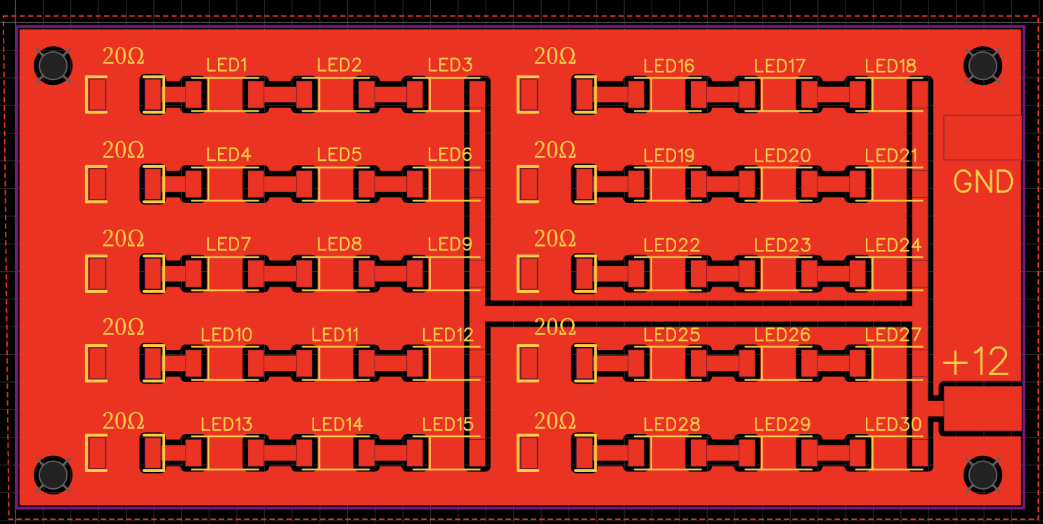

The copper layer which is all on the GND net, is underneath each LEDs heat dissipation node without any exposed copper so it will heat the entire copper plane that is GND electrically then presumably that will pass to the aluminum for dissipation...Last edited by EasyGoing1; 05-22-2021, 09:15 PM.Leave a comment:
-
-
-
Re: LED Resistor Calculations ...
I think you should look at your design to better take advantage of the copper front.Leave a comment:
-
-
Re: LED Resistor Calculations ...
I have a dead GE A19 bulb I need to take apart and do failure analysis...Leave a comment:
-
Re: LED Resistor Calculations ...
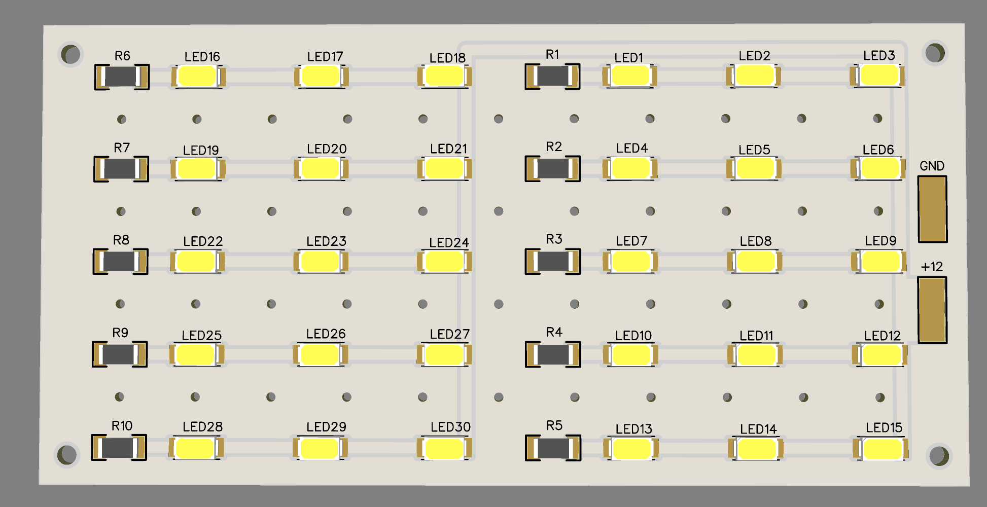
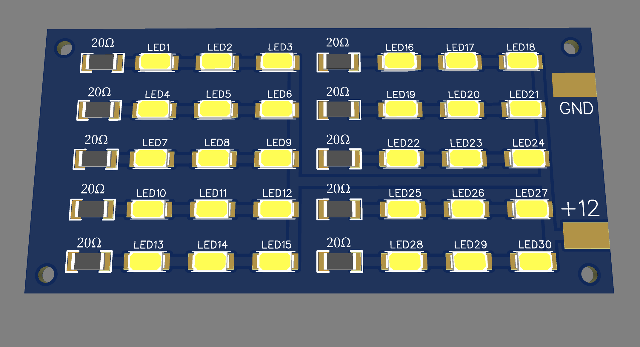
So I did some re-design on the panel, and I also made a 12-volt version ... everything on one layer without any center pins on the LED at all on the board, and I had originally had some through-hole components but when I had PCBWay quote them, they wanted over $300 ... so I made everything surface without any through-hole components and am waiting for that quote... apparently, when you spec aluminum for the board, it takes longer to get it quoted, but if the quote remains at the price it was when I put it in the cart, then ill order them up and should end up with a better panel that I have now.

Leave a comment:
-
Re: LED Resistor Calculations ...
Most high power LED dies have two bonding wires, with the die (substrate) glued or soldered to the cathode leg.
OP's having a third pad seems like it's just cheap or something.Attached FilesLeave a comment:
-
-
Re: LED Resistor Calculations ...
Yes, with large copper planes on the front and the back solid aluminium the whole PCB becomes a heatsink.Leave a comment:

-
 Dear community, I want to increase the lifespan of my backlight led in my TV by decreasing the current.
However I need some help identifying the resistor I need to replace to achieve this.
Thank you!
... -
 Hey everyone,
I'm currently working on a mid-70s Sharp Electronic Digital Clock Radio, Model FY-70CH. I found the service manual online, printed it out, and have been studying it for a while. My main reasons for tackling this are: (1) I want to learn electronics and figured I'd start with something I had on hand, and (2) I want to fix its issues. Right now, the radio sounds awful, has about 5V DC at the speaker terminals, and the alarm time setting doesn't work. But I'm not asking how to fix these problems.
Instead, here's what's been bugging me so far:
The schematic... -
 The resistor on this waterpik blew. I changed it with the a similar spec 47ohm 2 watt yageo resistor but it still keeps blowing the resistor. Checking with the multimeter the motor, capacitor, diodes, and thermal fuse all checked normal. Will a higher ohm resistor work better? What ohm resistor will work better to repair this waterpik? This video is showing the repair with a 56 ohm resistor https://www.youtube.com/watch?v=_J7_rV7ui1Y
 -
 Hi there !
I'm having an issue for several weeks with my quite old K70 LUX RGB keyboard. I haven't used it for few months, and once I setup up again my desktop computer, I got several dead LEDs on that keyboard. I tried the Corsair troubleshooting thing (disabling options in iCUE, ...) but nothing changed so I conclude that for some reason some LEDs went in retirement...😅
Decision taken to change these LEDs as I have access to desoldering iron and binocular magnifier, I wrote a ticket to tech support, hopping to obtain the LEDs reference and... They refused to tell me 🙄...10-08-2024, 11:58 AM -
 I have purchased an 100-240v AC/5v 2a DC adaptor from aliexpress,and a month ago It smelled burning when I plugin it powerstrip.
Since then, This AC/DC adaptor have been out of order.
But A few days ago,I replace 0.5 watt resistor with 1 watt resistor(1ohm) in this adapter.
After replacing resistor,It succeed to recharge all of android phone.And When I measure voltage on the two pins of USB port,It shows 5.5v
Is it okay to replace 1/2 watt resistor with 1 watt resistor in AC/DC adapter?
And Is there any possibility that it will suddenly explode as well as to be out...
Leave a comment: