Really new to this, think I messed up a board I'm working on

Collapse
X
 
  • Time
  • Show
Clear All
new posts
  • pavinski
    Start Hobbyist
    • Sep 2020
    • 3
    • UK

    #1

    Really new to this, think I messed up a board I'm working on

    Hey,

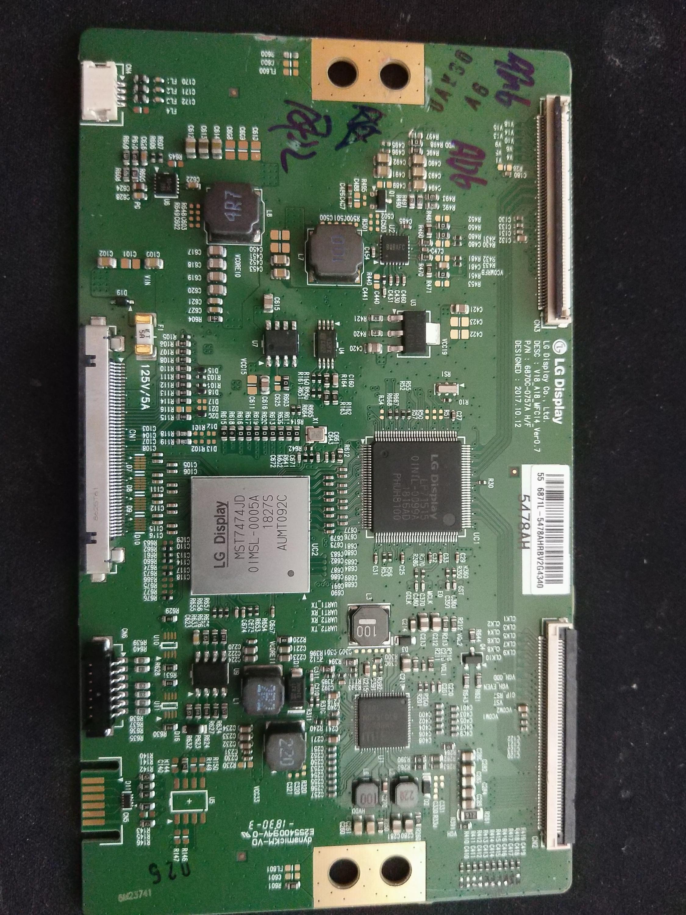
    I'm working a TCON board for my TV, unfortunately, I am unable to source the part I need, however, with a bit of modification, a board from a smaller unit in the same line can work instead.

    I have needed to remove some caps and eventually, swap out the EPPROM module between the two cards.

    I've only ever really worked on wires and bigger bits, so this is my first time needing to remove parts off the board, I've removed an array of caps that are needed to be removed. but I think I've completely frigged it up already.

    These are the pads from the removed caps:


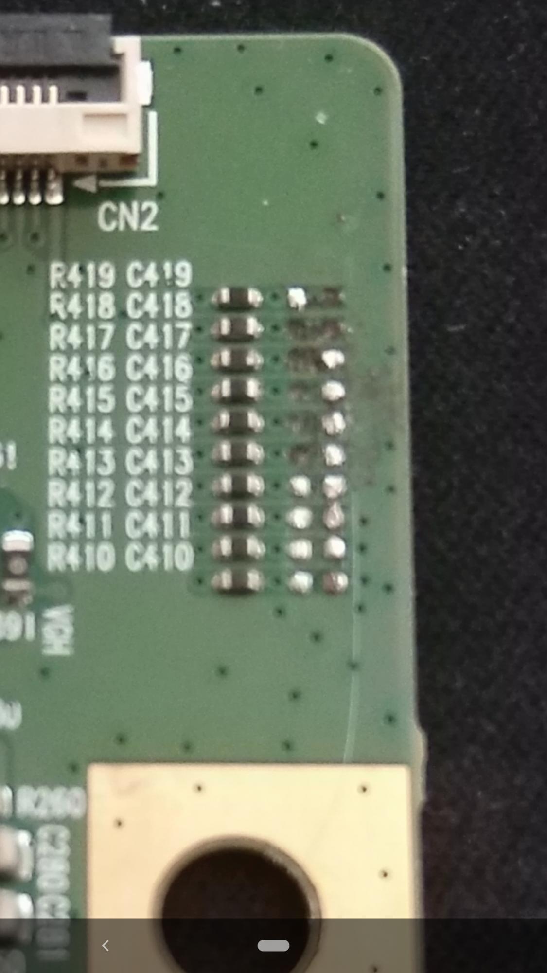
    It's work mentioning I don't need to replace these, so if I've not done any irripairable damage to the board, no problem other than need to really practice.

    Also - an additional question. Could someone tell me where the EPPROM module on this board? I know they're usually six-pin chips but I can count a couple on this board and they look identical, the numbers on them are damn near impossible to read too.


    Really appreciate the help

    Warmest
    Attached Files
  • sam_sam_sam
    Badcaps Legend
    • Jul 2011
    • 6037
    • USA

    #2
    Re: Really new to this, think I messed up a board I'm working on

    Can I ask you what type of soldering iron were you using

    You really need to use a temperature controlled tweeter soldering iron for this type of work

    Even using this type of iron you need to take your time and not get in a hurry doing this type of repair because some of these circuit board are real shit-e quality and if you put to much heat to the pads this will happen

    Now the way I do this is to have my iron hot enough that I grab the device and I can take it right off the board and not be on there more than 10 seconds

    I hope this helps you
    Last edited by sam_sam_sam; 09-06-2020, 08:27 AM.

    Comment

    • diif
      Badcaps Legend
      • Feb 2014
      • 6978
      • England

      #3
      Re: Really new to this, think I messed up a board I'm working on

      Seems the heat wasn't hot enough. They should just come off with a decent sized ball of molten solder on the end of your iron.
      The EEPROM has 8 legs, I'd guess it's the smallest of the three 8 legged components.
      I remove top lighting and light from the side to help read the writing on ICs.

      Comment

      • momaka
        master hoarder
        • May 2008
        • 12170
        • Bulgaria

        #4
        Re: Really new to this, think I messed up a board I'm working on

        Originally posted by pavinski
        These are the pads from the removed caps:

        https://www.badcaps.net/forum/attach...1&d=1599383087
        Yeah, those are done for, no offense.

        - If the pads came off very easily with the component while you were removing it, then your iron is probably too hot / too powerful.

        - If the pads came off because you used force to push the component while trying to desolder it, then your iron was either not hot enough or not transferring heat well to the board.

        Whichever the case, you don't necessarily need a temperature-controlled iron/station. I do most small SMD components like that with a plug-in, 30W unregulated soldering iron. 25-35W is typically enough for small SMD components. I don't suggest going any higher with the wattage over 35W. 40 will probably run too hot and lift pads as you experienced - that is, if it's not a temperature-controlled iron. Now, if you do have a temperature-controlled iron, then the power is not that important and you can easily go with anything (40-75W will do fine.) It's the temperature there that matters. For temperature-controlled irons, 330-350C is normal for just about any job, including SMD. The most important thing, however, is the tip that you use on your soldering iron. For SMD work, pencil/conical tips are just a pain. Chisel or bevel tip is what you should be using - preferably at least 2-3 mm wide. Or if your pencil/conical tip is made of copper, you can grind it down into a chisel tip (and thank me later. ) This is actually what's allowing me to use my cheapo 30W Radio Shack soldering iron "gun" for light SMD work, as I have ground/worn its original copper conical tip into a chisel/spoon shape.

        The second but very important thing is FLUX. Either get some Rosin or Rosin Mildly Activated (RMA) flux. Bonus points if it's labeled that it specifically works for SMD/BGA rework. Just stay away from Rosin Activated and Fully Activated ones, or anything touted as "Plumber's Flux", since these tend to be aggressive fluxes meant for soldering copper pipes in houses and will usually eat up the traces away on the PCB. Also try to avoid water-soluble fluxes, as some can be a pain to clean up. No-clean fluxes are OK.

        Originally posted by pavinski
        Also - an additional question. Could someone tell me where the EPPROM module on this board?
        Can't say for 100% sure, but it's likely either U4 or U9... or maybe (though unlikely) U7. If you read the part numbers off of those and look them up online, you should be able to find which one is the EEPROM. If you're struggling with that, post the part number here (as best as you can read them, as sometimes we know it's hard to read those SMD chips.)
        Last edited by momaka; 09-09-2020, 12:55 AM.

        Comment

        Related Topics

        Collapse

        • Tynan Dill
          Vizio e601i-A3 - Has Sound and Display, But No Backlight - Bad Power Supply Board or Bad LED Bulbs ?
          by Tynan Dill
          I was given this TV from my great uncle. He said it just wouldn't turn on one day out of nowhere, replaced the TV, and gave it to me to possibly fix and use for myself.

          Upon bringing it home and plugging it up, it showed a standby light.

          I powered it on and without a flashlight, the display showed the "V" but the lighting is very dim, but visible.

          The screen seems to blackout and stay black, but with a flashlight I can see the display.

          With my Playstation 4 connected via HDMI, and running a game I can hear sound.

          Assuming...
          11-22-2024, 01:46 PM
        • m1ch43lzm
          HP Pavilion 15-eh Board DAG7HAMB8F0 - CPU throttling to 0.4GHz (PROCHOT_EXT) and black screen
          by m1ch43lzm
          Hi, this is my personal laptop, which the original board (lets call it Board A) blew up PU8700 (TPS51486), making a hole on the board, i had left the laptop at my desk one day with the battery fully charged and didn't touch it for a week, but when i tried to turn it on it didn't
          Thought the battery was dead, so i plugged in the charger then tried to power on, the power LED blinked once, charged LED still orange, unplugged the charger, plugged in again and I noticed the "magic smoke" smell, so i unplugged the charger, removed the back cover and saw the blown IC (the "magic...
          05-12-2025, 08:37 PM
        • jb_Bak
          Sony xbr-65x900c main board issues?
          by jb_Bak
          Hey guys great forum glad to have found it. I bought a Sony XBR 65X900C cheaply because it didn't work. No signs of life at all not even a light/led. All I hear is a brief high voltage sound when I throw the power to it.

          Didn't see any obvious signs of damage so right away started checking voltages. This is what I see:
          Power Board Connector that goes to Main board
          CN6401
          Pin 01 NC
          Pin 02 NC
          Pin 03 "BL_ON": 0V
          Pin 04 "N/C"
          Pin 05 "STBY 3.3V": 3.5V
          Pin 06 "GND": N/C
          Pin 07 "AC_OFF"...
          09-27-2021, 04:52 PM
        • canadaboy25
          Panasonic TC-P54VT25 No image. A or D board?
          by canadaboy25
          I have a Panasonic TC-P54VT25 that will power on and prime the display but there is no image at all.

          The panel is primed as there is a slight glow from the entire panel. This means the problem should be logic related. The service manual also confirms this and recommends replacing the A or the D board.

          I have tried to get the TV to display the test sequence but I have been unable to and I don't even know if this TV has a test sequence or not. I tried following tom66's instructions in post #3 on this thread https://www.badcaps.net/forum/showthread.php?t=26790. There was...
          01-17-2021, 01:06 AM
        • sam_sam_sam
          Panasonic switching power supply daughter board has two 27uf @ 50 volt capacitors which I do not keep in stock
          by sam_sam_sam
          I did not have any 27uf @ 50 volt capacitors but one nice thing is that it has enough room for two capacitors in parallel a 22uf and a 4.7uf @ 50 volts 22 plus 4.7 equals 26.7uf which so very close to 27uf I will show some pictures of it sometime tomorrow

          This is one of the shit est boards I seen in a very long time and it was the daughter board the traces just lifting off the board I had to use the capacitor leads to repair the the traces and the main board is not any better because I had to repair several traces for the daughter board to the main board

          After all of...
          07-13-2024, 08:14 PM
        • Loading...
        • No more items.
        Working...