17IPS20 No LED Voltage Output

Collapse
X
 
  • Time
  • Show
Clear All
new posts
  • speedypro
    Badcaps Veteran
    • Feb 2013
    • 561
    • United Kingdom

    #1

    17IPS20 No LED Voltage Output

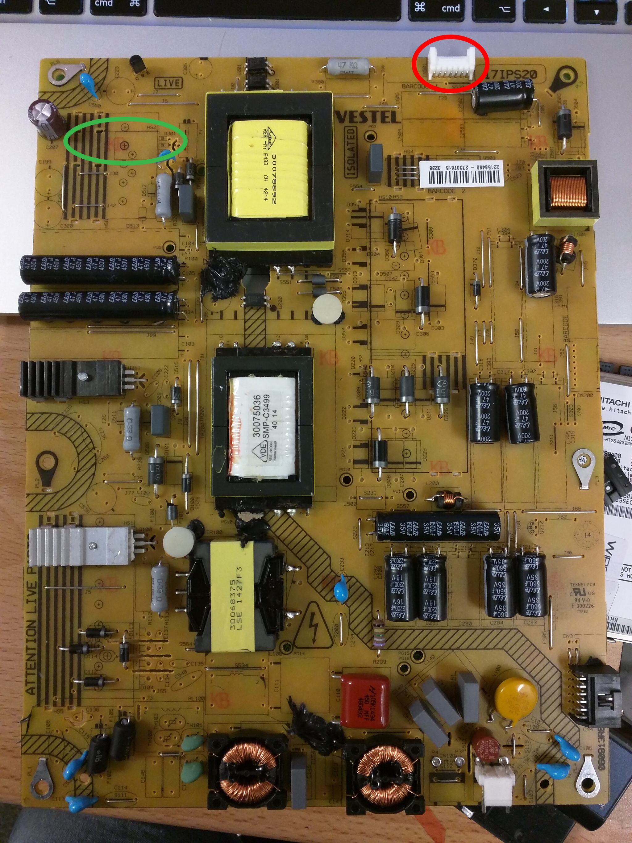
    Mine has no led voltage output (red circle)

    Green: took out for testing, it's ok.

    Image:


    Yellow: Change with new off ebay, same issue.


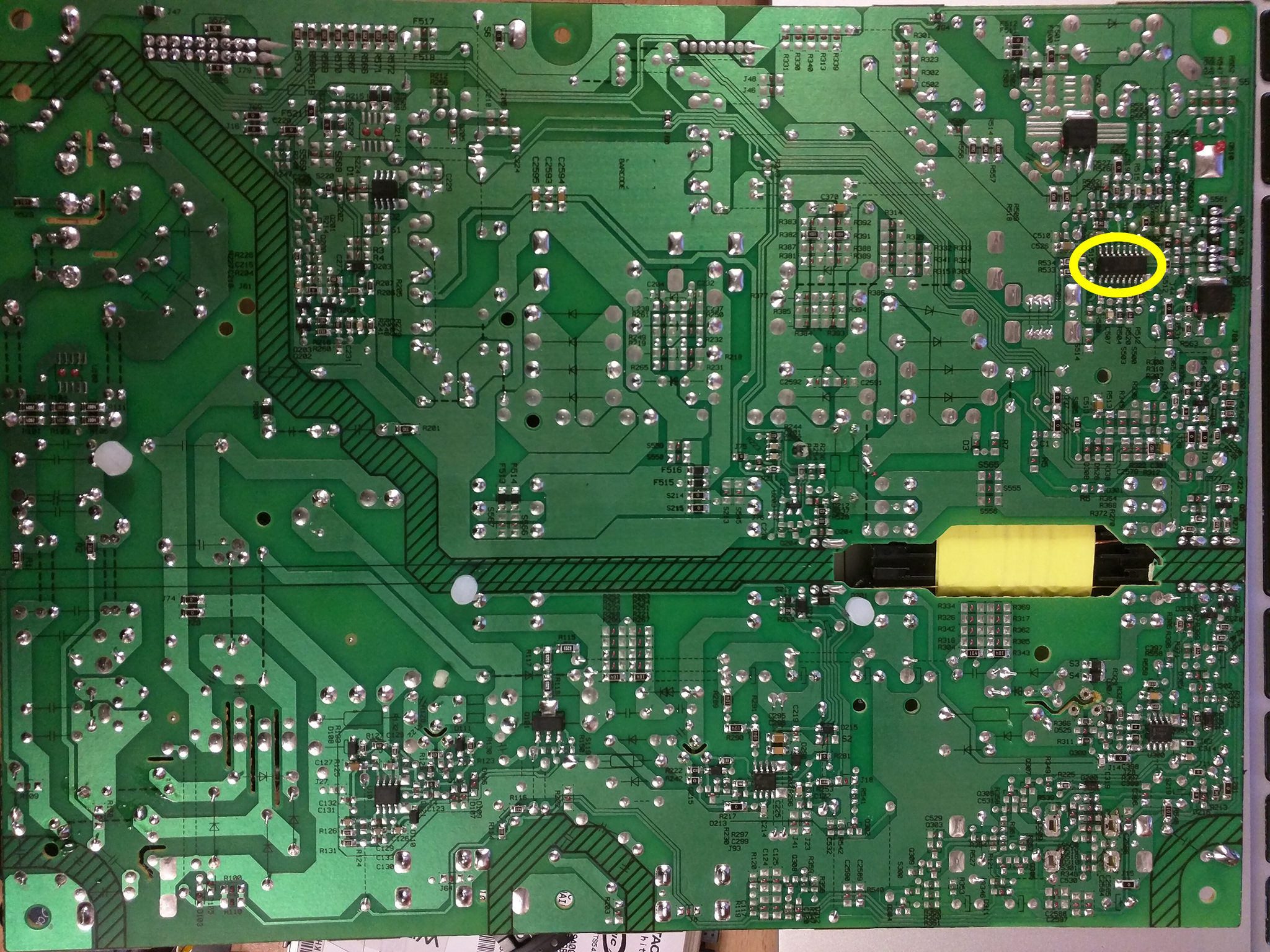
    Other two fets seems ok so never changed. Anything else to check, please?
    Attached Files
    Full-time computer repair tech (10am - 6pm) and full-time, (8am - 11pm), Ruby on Rails Developer
  • ReeceyBurger123
    Never Give Up !
    • May 2014
    • 7325
    • Britain

    #2
    Re: 17IPS20 No LED Voltage Output

    Change the Smps controller for that mosfet if thats failed the fet wont be turned on. Its a small chip near the mosfet on the bottom side of the Pcb. Also consider testing the led mosfet and diodes for S/C just incase. That controller turns on that fet for the Led circuit I have had this issue before will be doing video soon.
    Last edited by ReeceyBurger123; 07-02-2016, 06:55 AM.
    Please Do Not PM My Page Asking For Help Badcaps Is The Place For Advise, Page Linked For Business Reasons Only. Anyone Doing So Will Be Banned Instantly !

    https://www.facebook.com/Telford-Tel...7894576335359/

    Comment

    • speedypro
      Badcaps Veteran
      • Feb 2013
      • 561
      • United Kingdom

      #3
      Re: 17IPS20 No LED Voltage Output

      Hey. Where exactly? U201/U301? If you mean yellow circle: U500, done that but same.
      Last edited by speedypro; 07-02-2016, 07:00 AM.
      Full-time computer repair tech (10am - 6pm) and full-time, (8am - 11pm), Ruby on Rails Developer

      Comment

      • speedypro
        Badcaps Veteran
        • Feb 2013
        • 561
        • United Kingdom

        #4
        Re: 17IPS20 No LED Voltage Output

        More testing, I get 115VDC on the positive pin in red: A probe on + pin and a probe (-) on the negative part of the board. When I put both probes in red circle, no voltage. So something is faulty on the negative side in red circle.

        The cap beside the red circle, on the (+) pin, I get 115VDC.


        Attached Files
        Last edited by speedypro; 07-06-2016, 04:07 AM.
        Full-time computer repair tech (10am - 6pm) and full-time, (8am - 11pm), Ruby on Rails Developer

        Comment

        • tediee
          New Member
          • Jun 2018
          • 4
          • Slovenia

          #5
          Re: 17IPS20 No LED Voltage Output

          Originally posted by speedypro
          More testing, I get 115VDC on the positive pin in red: A probe on + pin and a probe (-) on the negative part of the board. When I put both probes in red circle, no voltage. So something is faulty on the negative side in red circle.

          The cap beside the red circle, on the (+) pin, I get 115VDC.


          speedypro , Did you find the solution for that "minus side issue" I had the exactly the same situation with my tv, I will be very grateful if you could share the solution with me...

          Comment

          • Andrew F. Ali
            Badcaps Legend
            • Jan 2014
            • 2450
            • Trinidad & Tobago

            #6
            Re: 17IPS20 No LED Voltage Output

            What are you saying...When you turn the TV with the RED probe on the +ve pin to the LEDs you have 115V wrt chassis GND and when you turn the TV with the RED probe on the -ve pin to the LEDs you have 0Vwrt chassis GND?

            Comment

            • tediee
              New Member
              • Jun 2018
              • 4
              • Slovenia

              #7
              Re: 17IPS20 No LED Voltage Output

              exactly, voltage measured between chassis GND and (+ve) is 115V and if you measure it between +ve and -ve on connector is 0 V.
              Last edited by tediee; 06-26-2018, 01:36 PM. Reason: typo

              Comment

              • budm
                Badcaps Legend
                • Feb 2010
                • 40746
                • USA

                #8
                Re: 17IPS20 No LED Voltage Output

                No Voltage reading between -Ve and GND means you have open circuit in the LED string some where.
                Never stop learning
                Basic LCD TV and Monitor troubleshooting guides.
                http://www.badcaps.net/forum/showthr...956#post305956

                Voltage Regulator (LDO) testing:
                http://www.badcaps.net/forum/showthr...999#post300999

                Inverter testing using old CFL:
                http://www.badcaps.net/forum/showthr...er+testing+cfl

                Tear down pictures : Hit the ">" Show Albums and stories" on the left side
                http://s807.photobucket.com/user/budm/library/

                TV Factory reset codes listing:
                http://www.badcaps.net/forum/showthread.php?t=24809

                Comment

                • tediee
                  New Member
                  • Jun 2018
                  • 4
                  • Slovenia

                  #9
                  Re: 17IPS20 No LED Voltage Output

                  hmm. I mean that I have disconnected the leds from power board connector. I measure it directly on power board pcb. So on the on the connector marked with red circle on picture (speedpro posted) on his last post.

                  If I measure on power board connector between +ve and -ve I got 115 V
                  If I measure on power board between connector +Ve and chassis GND I got 0V.

                  So I assume that there is sth on negative side...

                  Comment

                  • budm
                    Badcaps Legend
                    • Feb 2010
                    • 40746
                    • USA

                    #10
                    Re: 17IPS20 No LED Voltage Output

                    1) TV off
                    2) all connectors back in place.
                    3) Keep black probe on the chassis, red probe on the +ve then turn TV on and see how high the Voltage jumps up to, then turn TV OFF
                    4) Now move red probe to -VE, turn TV on and see how high the Voltage jumps up to.
                    5) Report those readings.
                    Never stop learning
                    Basic LCD TV and Monitor troubleshooting guides.
                    http://www.badcaps.net/forum/showthr...956#post305956

                    Voltage Regulator (LDO) testing:
                    http://www.badcaps.net/forum/showthr...999#post300999

                    Inverter testing using old CFL:
                    http://www.badcaps.net/forum/showthr...er+testing+cfl

                    Tear down pictures : Hit the ">" Show Albums and stories" on the left side
                    http://s807.photobucket.com/user/budm/library/

                    TV Factory reset codes listing:
                    http://www.badcaps.net/forum/showthread.php?t=24809

                    Comment

                    • tediee
                      New Member
                      • Jun 2018
                      • 4
                      • Slovenia

                      #11
                      Re: 17IPS20 No LED Voltage Output

                      Originally posted by budm
                      1) TV off
                      2) all connectors back in place.
                      3) Keep black probe on the chassis, red probe on the +ve then turn TV on and see how high the Voltage jumps up to, then turn TV OFF
                      4) Now move red probe to -VE, turn TV on and see how high the Voltage jumps up to.
                      5) Report those readings.
                      Results

                      3) black probe on the chassis, red probe on the +ve then turn TV - voltage jumps to 195V and that goes down to 115 V

                      4) red probe on -VE, turn TV on .
                      Voltage is constant on 11 V

                      Comment

                      • budm
                        Badcaps Legend
                        • Feb 2010
                        • 40746
                        • USA

                        #12
                        Re: 17IPS20 No LED Voltage Output

                        So the booster circuit kicks on 195V but then it goes into over Voltage shutdown so it goes back down to 115V which is the feeding Voltage to the input of the Boost converter circuits, you have open circuit in the LED string, wiring, connector problem some where.
                        Do you have LED tester to test the whole LED string?
                        Never stop learning
                        Basic LCD TV and Monitor troubleshooting guides.
                        http://www.badcaps.net/forum/showthr...956#post305956

                        Voltage Regulator (LDO) testing:
                        http://www.badcaps.net/forum/showthr...999#post300999

                        Inverter testing using old CFL:
                        http://www.badcaps.net/forum/showthr...er+testing+cfl

                        Tear down pictures : Hit the ">" Show Albums and stories" on the left side
                        http://s807.photobucket.com/user/budm/library/

                        TV Factory reset codes listing:
                        http://www.badcaps.net/forum/showthread.php?t=24809

                        Comment

                        Related Topics

                        Collapse

                        • electron_jj
                          Panasonic TH-L42D25A checking the PSU output voltage
                          by electron_jj
                          Hi Everyone, I am new to this forum. I have a Panasonic LED TV which doesnt turn on and is blinking 4 times repeatedly when I turn on the switch. The TV does not respond to the remote control so I had to turn on using the physical switch on the side of the TV. When I turn on the switch the 4 x blinking starts and repeat itself until I turn off the TV. There is a black screen. I turned off the light in the room to check the panel and I think there is no backlight as far as I can tell.

                          I have been inspecting and testing the capacitors and diodes in the power supply board to try to...
                          08-29-2021, 08:13 AM
                        • David Miteff
                          NM-D521 rev. 2.0 output voltage on CPU coils seemingly low
                          by David Miteff
                          Hello, guys!
                          As the title says - the board is NM-D521, on the input of the CPU coils I read 1.2-1.3V, which should be normal, but on the output I read around 0.6-0.8V. The laptop bootloops with no picture.
                          As of right now I don't have a thermal camera, so I can't confirm a shorted or partially shorted CPU chip. Do you have any other suggestions as of why the output voltage might drop like that?...
                          12-30-2024, 07:02 AM
                        • flibidy
                          Magnum IA.100 Amplifier Switches on, No Output, Possible Input Side fault?
                          by flibidy
                          I have here a Magnum IA.100 which belongs to my parents.


                          The unit powers on & when the relay kicks in, you get a pop from the speakers (this might sound weird but is usual behavior for this amp). However, you get nothing coming through it from any of the inputs & no pops and crackls from any of the controls.


                          Because of the sound from the speaker when the amp turns on I have assumed that the output section probably works but I could be wrong & I'm not sure how to test that side of things further.


                          What Ive done........
                          01-01-2025, 01:26 PM
                        • Document Archive
                          MT3608 Step-Up Converter IC Datasheet
                          by Document Archive
                          The MT3608 is a constant frequency, 6-pin SOT23 current mode step-up converter intended for small, low power applications. The MT3608 switches at 1.2MHz and allows the use of tiny, low cost capacitors and inductors 2mm or less in height.

                          Internal soft-start results in small inrush current and extends battery life.

                          The MT3608 features automatic shifting to pulse frequency modulation mode at light loads. The MT3608 includes under-voltage lockout, current limiting, and thermal overload protection to prevent damage in the event of an output overload. The MT3608 is available...
                          10-07-2024, 05:02 AM
                        • Ri5ux
                          Playstation 5 2 Second BLOD, F3501 Voltage Output Question
                          by Ri5ux
                          Hi there, just wondering if anyone out there who has a semi-working or working PS5 board could check the output voltage on F3501's buck converter for me, with and without power. I have 12V on the input, fuse not blown, no output voltage on that IC, with or without power, and no shorts present.

                          Symptom: 2 Second BLOD
                          Testing: All other rails seem present. APU, SSD, South Bridge, and RAM confirmed to be powering up using a thermal camera. Monitoring the current draw of the 12v rail shows a somewhat normal boot cycle of the south bridge. Jumps up to 300ma, and down to 0....
                          09-09-2023, 06:57 PM
                        • Loading...
                        • No more items.
                        Working...