Hi, I got a free Acer AL2423W LCD monitor from work, it was not working when I got it, there was nothing at all when I plugged in the power cable
I changed these capacitors on the power board and after that the backlight turns on and is lit properly, at this stage the monitor draws 51w at the power socket.
(Actually I cheated and did not replace the 10uF CapXon because I had problems removing the grounding shield, also I did not replace the 450v bulk filter cap next to it)
The two 100uF 25v capacitors sit at CS13 & CS16
Also I replaced 2x 1000uF 16v caps at position CS15 & CS14 with 1500uF caps
At positions CS10, CS11 & CS12 where United Chemi Con KY 25v 680uF caps that looked fine so I did not replace those...
So after these caps had been replaced the monitor turns the backlight on as soon as I give it power
However there is no picture displayed, either with or without a VGA or DVI cable
Also it is not possible to press any buttons, nothing happens, not even the standby button
At this stage I left it alone for several months but now when I saw the other 3 threads on this monitor with the bad Teapo caps on the logic board I decided to replace those, even tho they looked fine on my monitor.
However after removing them both their ESR and Capacitance was good (0.1 and 370uF respectively)
I recapped it anyway with Samxon GC 470uF 16v caps, 8 in total
I did not have a replacement for the 100uF 25v Teapo, however in circuit I measured it at 0.11ESR and 109uF
At this stage there was no difference from before, but I tried something I had not done before
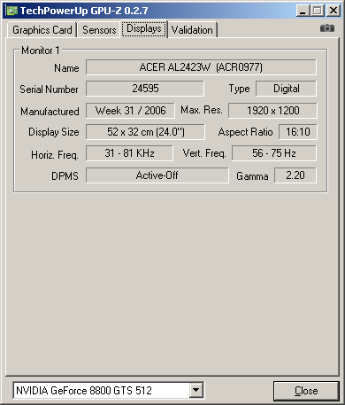
A added the GPU-Z monitorinfo program in the startup folder and shutdown my computer, next I stated it up with the Acer, which gave no picture still.
I waited untill the computer had finished loading and this is what I found when I connected back my Eizo LCD:
Lastly I measured the voltage at the underside of the PCB in the attached picture, I saw 19v, 12v and 5v at the middle of the Power Schottky rectifiers legs at each specific secondary output in the image (i.e. left, middle, and right arrow respectively)
If anyone has managed to read this far and would like to offer me some input on what to test next I would be very grateful!
I changed these capacitors on the power board and after that the backlight turns on and is lit properly, at this stage the monitor draws 51w at the power socket.
(Actually I cheated and did not replace the 10uF CapXon because I had problems removing the grounding shield, also I did not replace the 450v bulk filter cap next to it)
Code:
10uF	50v	CapXon KF
4,7uF	250v	CapXon KM
22uF	50v	CapXon KF
22uF	25v	CapXon GL
33uF	35v	CapXon GL (x2)
82uF	450v	CapXon KM
100uF  25v   CapXon KF (x2)
1000uF 16v   CapXon KF (x2)
Code:
Replacement Capacitors from Big Pope:
1 x 10uF  50V Samxon RS
1 x 4.7uF 250V Samxon RT
1 x 22uF  50V Samxon GF
1 x 22uF  25V Samxon RS
2 x 47uF  35V Samxon RS
2 x 100uF 25V Samxon GF
2 x 1500uF 16v Samxon GC
Also I replaced 2x 1000uF 16v caps at position CS15 & CS14 with 1500uF caps
At positions CS10, CS11 & CS12 where United Chemi Con KY 25v 680uF caps that looked fine so I did not replace those...
So after these caps had been replaced the monitor turns the backlight on as soon as I give it power
However there is no picture displayed, either with or without a VGA or DVI cable
Also it is not possible to press any buttons, nothing happens, not even the standby button
At this stage I left it alone for several months but now when I saw the other 3 threads on this monitor with the bad Teapo caps on the logic board I decided to replace those, even tho they looked fine on my monitor.
However after removing them both their ESR and Capacitance was good (0.1 and 370uF respectively)
I recapped it anyway with Samxon GC 470uF 16v caps, 8 in total
I did not have a replacement for the 100uF 25v Teapo, however in circuit I measured it at 0.11ESR and 109uF
At this stage there was no difference from before, but I tried something I had not done before
A added the GPU-Z monitorinfo program in the startup folder and shutdown my computer, next I stated it up with the Acer, which gave no picture still.
I waited untill the computer had finished loading and this is what I found when I connected back my Eizo LCD:
Lastly I measured the voltage at the underside of the PCB in the attached picture, I saw 19v, 12v and 5v at the middle of the Power Schottky rectifiers legs at each specific secondary output in the image (i.e. left, middle, and right arrow respectively)
If anyone has managed to read this far and would like to offer me some input on what to test next I would be very grateful!
Attached Files


 But today, I’m making an exception here. Why? No idea. Perhaps only because the repair details are still “fresh” in my head… which is ironic, given this is a 16 year old monitor that hardly anyone will care about today. It is new to me, though.


Comment