Schematic for IP-45130A (BN44-00127)

Collapse
X
Collapse
+ More Options
Posts
 
  • Time
  • Show
Clear All
new posts
  • MDOC
    EngineeringTech
    • Mar 2010
    • 146
    • USA

    #1

    Schematic for IP-45130A (BN44-00127)

    Anybody have a schematic for the power supply board found in Samsung's SyncMaster 226BW and similar model LCDs? The model number for these boards is IP-45130A. (BN44-00127x is Samsung's number for this board, with x = F or C and maybe other letters.)

    Thank you...
  • retiredcaps
    Badcaps Legend
    • Apr 2010
    • 9271

    #2
    Re: Schematic for IP-45130A (BN44-00127)

    Originally posted by MDOC
    Anybody have a schematic for the power supply board found in Samsung's SyncMaster 226BW and similar model LCDs? The model number for these boards is IP-45130A. (BN44-00127x is Samsung's number for this board, with x = F or C and maybe other letters.)
    What is wrong with it? I have this monitor sitting upstairs. I got it for free and for me, it was a simple recap.
    --- begin sig file ---

    If you are new to this forum, we can help a lot more if you please post clear focused pictures (max resolution 2000x2000 and 2MB) of your boards using the manage attachments button so they are hosted here. Information and picture clarity compositions should look like this post.

    We respectfully ask that you make some time and effort to read some of the guides available for basic troubleshooting. After you have read through them, then ask clarification questions or report your findings.

    Please do not post inline and offsite as they slow down the loading of pages.

    --- end sig file ---

    Comment

    • MDOC
      EngineeringTech
      • Mar 2010
      • 146
      • USA

      #3
      Re: Schematic for IP-45130A (BN44-00127)

      Two monitors, both 226BWs used in dual monitor configuration, need new caps. I already just fixed one of them, having just received my order for new caps. C110, C111, & C112 show signs of bulging and did not pass ESR values (too high). I replaced all but the big 450v cap. The only old cap that passed ESR is C107 (47uF). These were CapXons. The new ones are Panasonics.

      I wanted schematics so I can document oscilloscope displays between good & bad monitors.

      Comment

      • retiredcaps
        Badcaps Legend
        • Apr 2010
        • 9271

        #4
        Re: Schematic for IP-45130A (BN44-00127)

        Originally posted by MDOC
        I wanted schematics so I can document oscilloscope displays between good & bad monitors.
        Try

        http://elektrotanya.com/
        --- begin sig file ---

        If you are new to this forum, we can help a lot more if you please post clear focused pictures (max resolution 2000x2000 and 2MB) of your boards using the manage attachments button so they are hosted here. Information and picture clarity compositions should look like this post.

        We respectfully ask that you make some time and effort to read some of the guides available for basic troubleshooting. After you have read through them, then ask clarification questions or report your findings.

        Please do not post inline and offsite as they slow down the loading of pages.

        --- end sig file ---

        Comment

        • MDOC
          EngineeringTech
          • Mar 2010
          • 146
          • USA

          #5
          Re: Schematic for IP-45130A (BN44-00127)

          Originally posted by retiredcaps
          Joining that site was denied, it's by invitation only. But I have another member-only source of which I'm a member, I've sent an email about it. Thanks...

          Comment

          • budm
            Badcaps Legend
            • Feb 2010
            • 40746
            • USA

            #6
            Re: Schematic for IP-45130A (BN44-00127)

            You can download 2 max per day if you are not member.
            Never stop learning
            Basic LCD TV and Monitor troubleshooting guides.
            http://www.badcaps.net/forum/showthr...956#post305956

            Voltage Regulator (LDO) testing:
            http://www.badcaps.net/forum/showthr...999#post300999

            Inverter testing using old CFL:
            http://www.badcaps.net/forum/showthr...er+testing+cfl

            Tear down pictures : Hit the ">" Show Albums and stories" on the left side
            http://s807.photobucket.com/user/budm/library/

            TV Factory reset codes listing:
            http://www.badcaps.net/forum/showthread.php?t=24809

            Comment

            • MDOC
              EngineeringTech
              • Mar 2010
              • 146
              • USA

              #7
              Re: Schematic for IP-45130A (BN44-00127)

              OK, I did a search on ip-45130a and bn44-00127 and the search term was not found. But you know what? I think I found a substitute schematic with the right reference designations for caps on a different model number.
              Last edited by MDOC; 09-19-2012, 11:30 PM.

              Comment

              • retiredcaps
                Badcaps Legend
                • Apr 2010
                • 9271

                #8
                Re: Schematic for IP-45130A (BN44-00127)

                4 service manuals, but I did not download any so I don't know if they have schematics or not.

                http://elektrotanya.com/?q=showresul...oria=&kat2=all
                --- begin sig file ---

                If you are new to this forum, we can help a lot more if you please post clear focused pictures (max resolution 2000x2000 and 2MB) of your boards using the manage attachments button so they are hosted here. Information and picture clarity compositions should look like this post.

                We respectfully ask that you make some time and effort to read some of the guides available for basic troubleshooting. After you have read through them, then ask clarification questions or report your findings.

                Please do not post inline and offsite as they slow down the loading of pages.

                --- end sig file ---

                Comment

                • MDOC
                  EngineeringTech
                  • Mar 2010
                  • 146
                  • USA

                  #9
                  Re: Schematic for IP-45130A (BN44-00127)

                  They do have schematics, but none for the IP-45130A power supply/inverter board. When I saw that, I muttered, "Incomplete documentation." All they have is a reference to an "IP board." That's the one I want. I learned that the term "IP" is an acronym for "internal power".
                  Last edited by MDOC; 09-20-2012, 06:50 AM. Reason: more info

                  Comment

                  • jetadm123
                    Badcaps Legend
                    • Feb 2010
                    • 2169

                    #10
                    Re: Schematic for IP-45130A (BN44-00127)

                    Even when they do supply a schematic, many times it's different from the power supply that's actually in your monitor. This is because all the manufacturers have a tendency to use different power supplies in the same model monitor.

                    Comment

                    • MDOC
                      EngineeringTech
                      • Mar 2010
                      • 146
                      • USA

                      #11
                      Re: Schematic for IP-45130A (BN44-00127)

                      Well, now I'm back (I was away on a retreat trip). 5 days ago I poked around on the logic board on my second SyncMaster 226bw monitor with the flashing backlight syndrome in order to document the anomaly, and the power supply board (not the logic board) died on me: no flashing backlights, dead screen. I believe it's something before the 13V output on the power supply. I have since replaced the caps with no improvement (and I half-expected that). My other monitor (also a SyncMaster 226bw) is working fine after a cap replacement.


                      With the scope on R106 on the board (the 13V output side, the resister is at bottom left corner of the above photo on the power supply), this is what it looks like: first photo of a squarewave decreasing in frequency in 2 seconds to the frequency shown in the 2nd photo (both photos shown below):


                      Above: the starting AC ripple frequency when it snaps in from 13vdc. This is the AC ripple riding on top of the 13vdc level, the amplitude is 0.1v/div in this shot and the 2nd shot following. The timebase is 5uS/div.


                      Above: the ending frequency of a squarewave before it snaps back to DC level.


                      Above: one-second camera shutter exposure showing squarewave decreasing in frequency before it snaps off (13VDC level) for 7 seconds, then another 2 seconds of squarewave, then back to DC for 7 seconds, so on. The amplitude here is also 0.1v/div with the same timebase noted above.

                      Comment

                      • MDOC
                        EngineeringTech
                        • Mar 2010
                        • 146
                        • USA

                        #12
                        Re: Schematic for IP-45130A (BN44-00127)

                        Perhaps PlainBill would like to comment, too.

                        Comment

                        • budm
                          Badcaps Legend
                          • Feb 2010
                          • 40746
                          • USA

                          #13
                          Re: Schematic for IP-45130A (BN44-00127)

                          When you deal with high frequency and use the scope to look at the wave form, you will want your scope ground lead as close as possible to the ground point of what you are measuring, otherwise you will get false reading due to impedance of the ground, 1" inch of trace can have high impedance due to high frequency. You should put the ground lead right on the negative leg of the cap. You can verify if you are getting false reading by attach the ground lead of the probe to the tip of the probe and see what you can see on the screen when you move the probe around, that little loop will act as sensing coil.
                          Never stop learning
                          Basic LCD TV and Monitor troubleshooting guides.
                          http://www.badcaps.net/forum/showthr...956#post305956

                          Voltage Regulator (LDO) testing:
                          http://www.badcaps.net/forum/showthr...999#post300999

                          Inverter testing using old CFL:
                          http://www.badcaps.net/forum/showthr...er+testing+cfl

                          Tear down pictures : Hit the ">" Show Albums and stories" on the left side
                          http://s807.photobucket.com/user/budm/library/

                          TV Factory reset codes listing:
                          http://www.badcaps.net/forum/showthread.php?t=24809

                          Comment

                          • MDOC
                            EngineeringTech
                            • Mar 2010
                            • 146
                            • USA

                            #14
                            Re: Schematic for IP-45130A (BN44-00127)

                            That's true, but that has no bearing on the problem.

                            Comment

                            • budm
                              Badcaps Legend
                              • Feb 2010
                              • 40746
                              • USA

                              #15
                              Re: Schematic for IP-45130A (BN44-00127)

                              Well, since the power supply is an always on power supply, you can disconnect the logic board and see if the 13V is steady.
                              If it is still bad, then lift up one leg of the green fuse for the inverter circuits, this will remove the load from the power supply.
                              Last edited by budm; 09-24-2012, 06:22 PM.
                              Never stop learning
                              Basic LCD TV and Monitor troubleshooting guides.
                              http://www.badcaps.net/forum/showthr...956#post305956

                              Voltage Regulator (LDO) testing:
                              http://www.badcaps.net/forum/showthr...999#post300999

                              Inverter testing using old CFL:
                              http://www.badcaps.net/forum/showthr...er+testing+cfl

                              Tear down pictures : Hit the ">" Show Albums and stories" on the left side
                              http://s807.photobucket.com/user/budm/library/

                              TV Factory reset codes listing:
                              http://www.badcaps.net/forum/showthread.php?t=24809

                              Comment

                              • MDOC
                                EngineeringTech
                                • Mar 2010
                                • 146
                                • USA

                                #16
                                Re: Schematic for IP-45130A (BN44-00127)

                                Oh, the 13v is there, all right, whether you disconnect the logic board or the inverter circuit or both. It's just that the ripple is there, too, and I thought that shouldn't be there. The ripple is 0.2v p-p.

                                New development:
                                1) sawtooth waveform, picture shown below. This snaps into the squarewave I discussed earlier. Is the sawtooth normal?
                                2) I noticed now that some parts on the logic board like IC705 C744 C722 L703 are quite hot enough to burn you. Not normal. Appears to suggest I'm wrong about the power supply board being faulty. Any other suggestions? Thanks for the help.

                                What should the DC voltage across the big cap C105 on the power supply board be? I'm getting almost 170vdc out of it.

                                Below: sawtooth waveform riding on top of 13vdc. Amplitude is 5mV/div at 2 mS/div time.

                                Comment

                                • budm
                                  Badcaps Legend
                                  • Feb 2010
                                  • 40746
                                  • USA

                                  #17
                                  Re: Schematic for IP-45130A (BN44-00127)

                                  That is only 1.5% ripple (The ripple is 0.2v p-p), it is fine for inverter supply. The saw tooth waveform is normal, it showing the cap is charging and discharging.
                                  The 170V reading on the main cap is correct, it is the line voltage x 1.414 (you can ignore the 1.2V Vf of the two rectifier diode).
                                  "IC705 C744 C722 L703 are quite hot enough to burn you" the caps should not get hot.
                                  You can force the backlights inverter to turn on by putting a resistor (2.2K) between the 13V (this power supply board does not have 5V output) Line and the BL_ON LINE (the logic board will have to be disconnected so the we do not flow back into the main board)
                                  Never stop learning
                                  Basic LCD TV and Monitor troubleshooting guides.
                                  http://www.badcaps.net/forum/showthr...956#post305956

                                  Voltage Regulator (LDO) testing:
                                  http://www.badcaps.net/forum/showthr...999#post300999

                                  Inverter testing using old CFL:
                                  http://www.badcaps.net/forum/showthr...er+testing+cfl

                                  Tear down pictures : Hit the ">" Show Albums and stories" on the left side
                                  http://s807.photobucket.com/user/budm/library/

                                  TV Factory reset codes listing:
                                  http://www.badcaps.net/forum/showthread.php?t=24809

                                  Comment

                                  • MDOC
                                    EngineeringTech
                                    • Mar 2010
                                    • 146
                                    • USA

                                    #18
                                    Re: Schematic for IP-45130A (BN44-00127)

                                    Where is this BL_ON line on the power supply board? Are you talking about ON/OFF at pin 9 of CN2 connector which connects to the logic board? If so, that's 3.3V from the logic board. But if not, can you provide another ref on the board, such as a resister or other component junction with BL_ON? Or are you referring to enabling the inverter controller (OZ964GN) via pin 3 (ENA)?

                                    Comment

                                    • MDOC
                                      EngineeringTech
                                      • Mar 2010
                                      • 146
                                      • USA

                                      #19
                                      Re: Schematic for IP-45130A (BN44-00127)

                                      Well, the last monitor's fixed and working. There was a short on the main board (I called it the logic board earlier). I replaced it rather than trying to find the short, since the replacement was cheap.

                                      Initially, both monitors were exhibiting rapidly flashing backlighting. This was caused by capacitors drying out, and I replaced those. This fixed my first of two monitors but the second monitor developed another problem, probably caused by my unsteady hand probing the main (logic) board with a scope probe. I wanted to document the anomally.

                                      The caps were made by CapXon. I replaced them with Panasonic.


                                      Above: The flashing backlighting was caused by these caps.


                                      While troubleshooting around the main board, I found that the schematics from the Samsung service manual for my 226BW monitor were the wrong ones, though I had specified the correct Samsung model number. Two things support this fact: schematic is different from what was actually on the board, and some parts are not in the parts list.


                                      Above: showing part of the schematic I was working with before I discovered it was the wrong one.


                                      Above: The correct schematic now has a schottky diode (D702) where the previous one didn't. And it wasn't listed in the parts list.


                                      The cover page of one service manuals listed more chassis and model numbers than the other, but my monitor model number (226BW) was included in both. So I thought the schematic from both were redundant. I was wrong. In fact, schematics and parts lists are different, yet the copyright date from both manuals are the same!


                                      Above: from the "wrong" service manual.


                                      Above: from the "correct" service manual. Same copyright date but different text.


                                      Anyway, in my previous post, I showed a pix showing sawtooth pattern waveform. After fixing my monitor, I took another look and saw a different pattern (albeit somewhat similar). This is not to say that the sawtooth was incorrect, only to say that the sawtooth was not a normal waveform to expect from a working monitor. The sawtooth is what you see if the main board is either not working or disconnected from the power board.

                                      Below is the normal waveform riding on top of the 13V.

                                      Above: Note that the frequency is a little different, too. Same scope parameters as the sawtooth pix in the earlier post. Scope input was on AC, not DC.


                                      Above: where the waveform was monitored on the power board. I discovered that the two heatsinks on the board are tied to ground, so this was a better place to put the ground clip than on the corner of the main board.


                                      Above: Ripple from the ON/OFF on pin 9 of CN2 on the power board (refer to previous pix for location). 0.1V/div 50uS/div, scope input set to AC. This is the 5V from the main board.


                                      Below: my two monitors are now working.

                                      Comment

                                      Related Topics

                                      Collapse

                                      • TinkerTron
                                        Schematic vs. Reality: Where Are the Resistors on My Sharp Clock Radio? Model FY-70CH
                                        by TinkerTron
                                        Hey everyone,

                                        I'm currently working on a mid-70s Sharp Electronic Digital Clock Radio, Model FY-70CH. I found the service manual online, printed it out, and have been studying it for a while. My main reasons for tackling this are: (1) I want to learn electronics and figured I'd start with something I had on hand, and (2) I want to fix its issues. Right now, the radio sounds awful, has about 5V DC at the speaker terminals, and the alarm time setting doesn't work. But I'm not asking how to fix these problems.

                                        Instead, here's what's been bugging me so far:
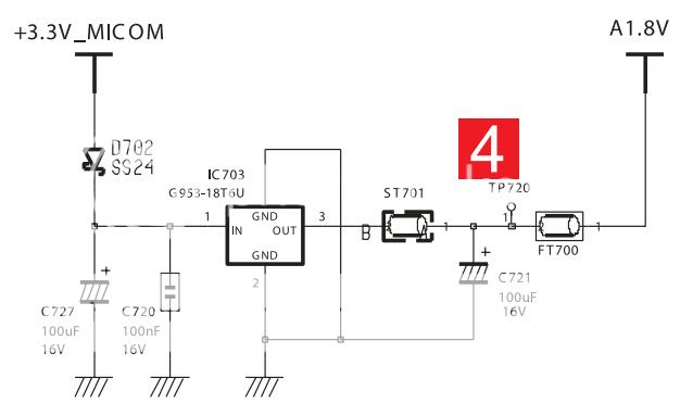
                                        The schematic...
                                        03-06-2025, 02:03 PM
                                      • atunguyd
                                        Acer x163w Monitor PSU schematic
                                        by atunguyd
                                        Ii wonder if anyone can help me. I have a Acer x163w monitor which is not powering up. The PSU main capacitor's one leg had completly come off - I replaced it but the PSU is still not outputting DC. I found the monitor in questions service manual here on manuals lib but the schematic in there is a completely different - the schematic shows no mosfet to drive the transformer while the one I have does use a mosfet - also the schematic shows only one optocoupler but mine has two.
                                        The PSU board is labelled FM-20A02-AAA made by APD as per the image below. I am trying to find a schematic for this...
                                        03-05-2025, 02:08 PM
                                      • BSamvelov
                                        Bios that supports Title letters in password on disk
                                        by BSamvelov
                                        Hi everyone. I used Acer Travelmate 6292 with BIOS v.13112, Santa Rosa 1436 (VGA Bios version). This BIOS supported title letters for creating password on HDD.
                                        A week ago an element on textolite burnt and I cant turn on laptop.
                                        I thought that title letters support different types of BIOS.
                                        I tried my new laptop lenovo and my friends old Acer and to regret nor mine nor his laptop doesnt support title letters in
                                        Standart HDD 2,5 inches.
                                        How can this problem be resolved?
                                        Lots of BIOS versions of different types of laptops support title letters in password?...
                                        05-18-2024, 03:51 AM
                                      • Thetechdude
                                        MSI Ventus RTX 4080 16G Broadview schematic needed
                                        by Thetechdude
                                        Hi guys, I'm working on a MSI Ventus RTX 4080 16G. The GPU has 12v, 5v, however what I assume is the 1.8v rail has 1.1v and what I assume to be PEX is 0v. As you may have guessed already there is no Vmem and no Vcore.

                                        I have looked around in related forum posts for a schematic so Much appreciated if anyone can share a Broadview schematic.

                                        Thanks.
                                        Yesterday, 11:15 AM
                                      • ianpoultonknights
                                        Zenbook Flip 15 UX562AI schematic
                                        by ianpoultonknights
                                        Had one of these come in for repair with a blown battery and a WiFi issue, battery has been replaced with genuine battery (twice) and won't take a charge works fine on AC, WiFi issue gone away. Looking for a schematic so I can trace the charger circuit UM562F is only one I can find, this is the 562AI model.Had a unit come in for repair — 562AI model — with a blown battery and WiFi issue. WiFi fault has cleared, but battery won’t charge despite replacing it twice with genuine parts. Device operates fine on AC power. Suspect charger circuit fault. Only schematic I’ve found so far is for...
                                        06-26-2025, 02:41 PM
                                      • Loading...
                                      • No more items.
                                      Working...