Announcement

Collapse
No announcement yet.

Arduino current sensing (in car)

Collapse
X
 
  • Filter
  • Time
  • Show
Clear All
new posts

    #61
    Re: Arduino current sensing (in car)

    Thanks for the input guys. This is one of the reasons I wanted to build that adjustable load a while back...I actually found one on Banggood pre-made, but it's not exactly cheap, so I'm not sure it would be worth the investment and pay for itself in the long run.
    Wattevah...

    Comment


      #62
      Re: Arduino current sensing (in car)

      Originally posted by Dannyx View Post
      This is one of the reasons I wanted to build that adjustable load a while back...I actually found one on Banggood pre-made
      Could you please post the link to Item that you are taking about

      Thanks

      Comment


        #63
        Re: Arduino current sensing (in car)

        Yes. Here it is. This also qualifies as a bit of a fail, since I recalled it being much more expensive than that, but looking at it NOW, it doesn't seem unreasonable (its price could've dropped indeed). When dealing with stuff like this I always put it like this: make or buy: would the cost of the components required to build one myself outweigh the pre-made version ? If so, I'd definitely choose the ready-made version...
        Last edited by Dannyx; 05-11-2018, 07:24 AM.
        Wattevah...

        Comment


          #64
          Re: Arduino current sensing (in car)

          I going buy few of them to how they work

          Comment


            #65
            Re: Arduino current sensing (in car)

            It looks reasonable by the time you add heatsink, control pot, and may be fan and the case for may be $20 and if it works really well, then it is great.
            Never stop learning
            Basic LCD TV and Monitor troubleshooting guides.
            http://www.badcaps.net/forum/showthr...956#post305956

            Voltage Regulator (LDO) testing:
            http://www.badcaps.net/forum/showthr...999#post300999

            Inverter testing using old CFL:
            http://www.badcaps.net/forum/showthr...er+testing+cfl

            Tear down pictures : Hit the ">" Show Albums and stories" on the left side
            http://s807.photobucket.com/user/budm/library/

            TV Factory reset codes listing:
            http://www.badcaps.net/forum/showthread.php?t=24809

            Comment


              #66
              Re: Arduino current sensing (in car)

              I also found pots on Banggood. Multiturn ones for reasonable prices (especially considering Banggood mostly sells multiple pieces for a low price)
              Wattevah...

              Comment


                #67
                Re: Arduino current sensing (in car)

                Originally posted by Dannyx View Post
                I also found pots on Banggood. Multiturn ones for reasonable prices (especially considering Banggood mostly sells multiple pieces for a low price)
                Could you please post the link to it thanks

                Comment


                  #68
                  Re: Arduino current sensing (in car)

                  Have a look through the results yourself HERE and see what catches your eye
                  Wattevah...

                  Comment


                    #69
                    Re: Arduino current sensing (in car)

                    That load I linked to looks like it's got two op-amps on it....a double amplifier configuration perhaps ? I think I'll go for it myself
                    Wattevah...

                    Comment


                      #70
                      Re: Arduino current sensing (in car)

                      Originally posted by Dannyx View Post
                      Have a look through the results yourself HERE and see what catches your eye

                      Thank you for the link

                      This is the one I going to buy


                      https://m.banggood.com/3590S-2-103L-...ottom-alsolike

                      Comment


                        #71
                        Re: Arduino current sensing (in car)

                        Originally posted by Dannyx View Post
                        That load I linked to looks like it's got two op-amps on it....a double amplifier configuration perhaps ? I think I'll go for it myself

                        I saw that to that why I going to give it a try my self

                        Comment


                          #72
                          Re: Arduino current sensing (in car)

                          Yep - that's the one I chose myself...looks decent enough.
                          Wattevah...

                          Comment


                            #73
                            Re: Arduino current sensing (in car)

                            Dang, I haven't used a multiturn pot in ages... I have two or so in my junkbox but none in any equipment...

                            Comment


                              #74
                              Re: Arduino current sensing (in car)

                              I just received those current sensors I ordered...haven't messed around with them yet, but in the meantime, my code reaching completion, I still haven't decided what the best course of action is regarding the different inputs: should I use "active high" or "active low" ? That is, should the pins read off when LOW or off when HIGH ? Power consumption is important, because the thing will be running on the car's battery, plus it has to be relatively noise-resistant, and in this regard I did some research and learned that the simplest form of debouncing is to add a capacitor between the pin and GND, of course this would require the "active low" setup, which is what I currently got going on on the breadboard, but how it will behave in the actual vehicle I have no idea....
                              Wattevah...

                              Comment


                                #75
                                Re: Arduino current sensing (in car)

                                active low,
                                if you use active high you need to screw around with voltage clamping and other shit.

                                Comment


                                  #76
                                  Re: Arduino current sensing (in car)

                                  I still need to clamp it to 5v anyhow, since I can't pull up or supply the board with more than that.
                                  Wattevah...

                                  Comment


                                    #77
                                    Re: Arduino current sensing (in car)

                                    When I have done projects with a Basic Stamp I always use active high ( meaning do some part of the program )

                                    Comment


                                      #78
                                      Re: Arduino current sensing (in car)

                                      Originally posted by Dannyx View Post
                                      I still need to clamp it to 5v anyhow, since I can't pull up or supply the board with more than that.
                                      pullups enabled on the microcontroller, and inputs connected through diodes - job done.

                                      Comment


                                        #79
                                        Re: Arduino current sensing (in car)

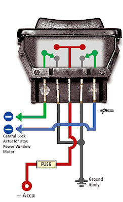
                                        It's a little more complicated than that, since I'm going to be using the existing rocker switches in the dash, but instead of connecting their outputs to the windows (like they are now), I'll connect them to the micro....right away there's a lot of difficulties: active low is not possible in this setup straight away, because if you know how a window rocker switch operates you know it keeps the outputs (the wires going into the actual motor) grounded at all times when not in use. When you flip it in one direction, one of the wires continues to remain grounded, while the other one is pulled high to VCC, so the motor goes in one direction. When rocked in the other direction, the wire which was VCC goes to GND and vice versa.

                                        So imagine the green and blue wires go to the motor in the door (don't mind the text, except the GND and VCC which are accurate), so what I'll do is cut them, put some connectors on them to make the install easier, then connect them to a NPN transistor each: one for UP, one for DOWN. When pressed in one direction, let's say "UP", 12v will go into the base of the "UP" transistor, pulling the E-C path to GND and the micro's "UP" pin with it, activating the corresponding pin of the H-bridge we'll be putting in. Meanwhile, the "DOWN" transistor's base remains grounded through the other wire which used to go to the motor....that's the theory at least.


                                        Trouble is, I'm not sure it will work to begin with and what trannies to use after the fact, especially since I'm using them somewhat opposite of how they're normally used: I'm switching a LOW signal with a HIGH signal, which brings us to problem no.2: the car operates at 12-15v (when running)....no need to say more. The buck converters I got off banggood should do the job of powering the while providing sufficient noise suppression....I hope....that's why I'm sharing this project, to hear other peoples' opinions and hopefully build it as robustly as possible.
                                        Granted, if I knew what I was doing, I wouldn't be posting asking for advice and it wouldn't be nearly as fun...half the fun is figuring out all this sh!t...some people hate it, but I like it...I love tinkering to waste time
                                        Wattevah...

                                        Comment


                                          #80
                                          Re: Arduino current sensing (in car)

                                          connect the red to ground and the blue & green to the mcu.

                                          Comment

                                          Working...