
Re: Help identifying this chip - battery controller chip ?
I ended up with using a htc 1200mAh battery - everything is working as it should, posted a update in this thread link
Thanks for the help fzabkar.
-
Re: Help identifying this chip - battery controller chip ?
I think you need to find where the system stores the original parameters of the battery pack. Maybe these are interfering with the current parameters. Try searching your files or registry for the battery's serial number, etc.Leave a comment:
-
Re: Help identifying this chip - battery controller chip ?

Ok, I got it working.
Design capacity is not changed back to 1215 and stays at 1800, after first calibration full capacity is now at 1909mAh.

After second calibration full capacity reaches 1925mAh.

Not sure it is a problem with hex code or normal feature of this software but charging stops as 49% but battery status is 'optimal', I will ask at a few raid forums what capacity their original ibb07 stops charging at.
If I remember correctly turning off automatic learn mode I can charge the battery up to 100% but if status will then be 'Degraded'.Leave a comment:
-
Re: Help identifying this chip - battery controller chip ?
Sorry, I don't understand what is happening, or why. :-(Leave a comment:
-
Re: Help identifying this chip - battery controller chip ?
Hehe yes it is, it must be software or fw on the raidcard itself.
I need to remove the chip again, this time just for a test I will let the packconfiguration be 64hex (sealed) and see if the software manages to change it back to 1215.
I don't think anything else is changed but I will dump the eeprom again to see.
However my goal was to make use of defective battery packs and it is possible to replace battery and reprogram eeprom when battery pack is defective but then I need to have access to a Sony US503759 a8h 1350mAh or similar type.
If I keep the capacity at 1215mAh I'm 99% sure I will have no problem re-using these packs.Last edited by Gabriel; 01-24-2016, 02:36 PM.Leave a comment:
-
Re: Help identifying this chip - battery controller chip ?
I don't understand why the software would want to change a design parameter, nor do I understand where the 1215mAh value would be stored. Very strange ...
Can your TI software change the design capacity back to 1800mAh, or do you now need to remove the EEPROM again? Have any of your other EEPROM modifications been undone?Last edited by fzabkar; 01-24-2016, 01:49 PM.Leave a comment:
-
Re: Help identifying this chip - battery controller chip ?
Flashed back the modified content and fitted battery.

I bought a interposer kit for the battery to move the battery away from the raid card itself to keep the battery cooler - it also makes it easy to measure directly on the battery.

Raid web bios, everything seems to be right - new data is reported correctly.

Storage manager in windows reports are ok - battery is now charging with 438mA.

Battery almost fully charged at 4.1V, charging current is only 55mA and it will now start to discharge.

Something is wrong, battery capacity suddenly changed to back to 1215mAh.

Command timeout and unexpected sense errors in log.
Code:ID = 148 SEQUENCE NUMBER = 343 TIME = 16-01-2016 23:45:31 LOCALIZED MESSAGE = Controller ID: 0 Battery is discharging ID = 113 SEQUENCE NUMBER = 342 TIME = 16-01-2016 23:44:31 LOCALIZED MESSAGE = Controller ID: 0 Unexpected sense: PD = -:-:0Power on, reset, or bus device reset occurred, CDB = 0x8f 0x00 0x00 0x00 0x00 0x01 0x45 0x31 0x10 0x00 0x00 0x00 0x10 0x00 0x00 0x00 , Sense = 0x70 0x00 0x06 0x00 0x00 0x00 0x00 0x0a 0x00 0x00 0x00 0x00 0x29 0x00 0x00 0x00 0x00 0x00 ID = 113 SEQUENCE NUMBER = 341 TIME = 16-01-2016 23:44:31 LOCALIZED MESSAGE = Controller ID: 0 Unexpected sense: PD = -:-:1Power on, reset, or bus device reset occurred, CDB = 0x8f 0x00 0x00 0x00 0x00 0x01 0x42 0x92 0x40 0x00 0x00 0x00 0x10 0x00 0x00 0x00 , Sense = 0x70 0x00 0x06 0x00 0x00 0x00 0x00 0x0a 0x00 0x00 0x00 0x00 0x29 0x00 0x00 0x00 0x00 0x00 ID = 113 SEQUENCE NUMBER = 340 TIME = 16-01-2016 23:44:30 LOCALIZED MESSAGE = Controller ID: 0 Unexpected sense: PD = -:-:0Power on, reset, or bus device reset occurred, CDB = 0x8f 0x00 0x00 0x00 0x00 0x01 0x45 0x30 0x30 0x00 0x00 0x00 0x10 0x00 0x00 0x00 , Sense = 0x70 0x00 0x06 0x00 0x00 0x00 0x00 0x0a 0x00 0x00 0x00 0x00 0x29 0x00 0x00 0x00 0x00 0x00 ID = 113 SEQUENCE NUMBER = 339 TIME = 16-01-2016 23:44:30 LOCALIZED MESSAGE = Controller ID: 0 Unexpected sense: PD = -:-:1Power on, reset, or bus device reset occurred, CDB = 0x8f 0x00 0x00 0x00 0x00 0x01 0x42 0x91 0x20 0x00 0x00 0x00 0x10 0x00 0x00 0x00 , Sense = 0x70 0x00 0x06 0x00 0x00 0x00 0x00 0x0a 0x00 0x00 0x00 0x00 0x29 0x00 0x00 0x00 0x00 0x00 ID = 268 SEQUENCE NUMBER = 338 TIME = 16-01-2016 23:44:30 LOCALIZED MESSAGE = Controller ID: 0 PD Reset: PD = -:-:1, Critical = 3, Path = 0x4433221102000000 ID = 268 SEQUENCE NUMBER = 337 TIME = 16-01-2016 23:44:30 LOCALIZED MESSAGE = Controller ID: 0 PD Reset: PD = -:-:0, Critical = 3, Path = 0x4433221103000000 ID = 151 SEQUENCE NUMBER = 336 TIME = 16-01-2016 23:44:30 LOCALIZED MESSAGE = Controller ID: 0 Battery relearn started ID = 267 SEQUENCE NUMBER = 335 TIME = 16-01-2016 23:44:28 LOCALIZED MESSAGE = Controller ID: 0 Command timeout on PD: PD = -:-:1No addtional sense information, CDB = 0x8f 0x00 0x00 0x00 0x00 0x01 0x42 0x91 0x10 0x00 0x00 0x00 0x10 0x00 0x00 0x00 , Sense = , Path = 0x4433221102000000 ID = 267 SEQUENCE NUMBER = 334 TIME = 16-01-2016 23:44:28 LOCALIZED MESSAGE = Controller ID: 0 Command timeout on PD: PD = -:-:0No addtional sense information, CDB = 0x8f 0x00 0x00 0x00 0x00 0x01 0x45 0x30 0x20 0x00 0x00 0x00 0x10 0x00 0x00 0x00 , Sense = , Path = 0x4433221103000000 ID = 242 SEQUENCE NUMBER = 333 TIME = 16-01-2016 23:44:16 LOCALIZED MESSAGE = Controller ID: 0 Battery charge complete

Battery discharging and is now @3625mV - fluke measures 3646mV.

Battery discharging and is now @3567mV - fluke measures 3588mV.

Battery discharging and is now @3443mV - fluke measures 3443mV.
Getting worried and turn computer off to save battery as this is a raw cell without protection circuit.
Now I wonder what would happen if I repogram the lc2401 with same hex code but with code sealed, then software/driver should not be able to change design capacity back to 1215mAh.Leave a comment:
-
Re: Help identifying this chip - battery controller chip ?
AIUI, the battery pack communicates its status via the SMBus BatteryStatus command (0x16, page 33). This word reports alarm, status and error codes. It is presumably stored in the IC's RAM.
The Pack Status and Pack Configuration command (0x2f, page 38) reports the Pack Status in the upper byte and Pack Configuration in the lower byte. The Pack Configuration is retrieved from offset 0x3F in the EEPROM whereas the Pack Status appears to be RAM based.Leave a comment:
-
Re: Help identifying this chip - battery controller chip ?
Bit 6 is the SEAL bit. A value of 0x64 for the Pack Configuration Byte sets the SEAL bit whereas a value of 0x24 resets this bit. AIUI, you need to select 0x24 until you have finished "tampering", then you can seal the EEPROM.
0x24 = 0b00100100 <- unSEALed
0x64 = 0b01100100 <- SEALed
BTW, "batterystatus" and "pack configuration" are not the same thing.
Just in case you need the user guide ...
https://cdn.badcaps-static.com/pdfs/...e97a1918e5.pdf
The "Battery Backup Unit Related Properties" are documented in section 2.6. Unfortunately there is no documentation for "MegaCli -AdpBbuCmd -BbuMfgSeal -aN|-a0,1,2|-aALL".Leave a comment:
-
Re: Help identifying this chip - battery controller chip ?
Are you sure about the bits in batterystatus ? 0b01100100
I was reading this, how did you come up with 24hex instead of 64hex ?
No, not sure I really need to seal it again-this bit can be 0 while in development but should always be set to a 1 when the part is in the field so yes I guess it is to prevent tampering.Last edited by Gabriel; 01-22-2016, 03:26 PM.Leave a comment:
-
Re: Help identifying this chip - battery controller chip ?
I use Google's calculator.
http://www.google.com.au/search?q=69+-+0xC+x+1.6
http://www.google.com.au/search?q=0x...A60+in+decimal
http://www.google.com.au/search?q=0x24+in+binary
http://www.google.com.au/search?q=650+in+hex
BTW, do you really need to seal the EEPROM contents? Why not just leave them unsealed? I would think that sealing is only implemented by the manufacturer to prevent tampering by you.Last edited by fzabkar; 01-22-2016, 03:08 PM.Leave a comment:
-
Re: Help identifying this chip - battery controller chip ?
I see that I still have some hex/math to read up on.
I will flash back the modified content I posted above tomorrow,see what happens and come back with a report.
Also, since the eeprom is now unsealed I have been googling a solution to seal it again after a successfull calibration and it should be possible in dos with the commands below.
MegaCli -AdpBbuCmd -aN|-a0,1,2|-aALL
MegaCli -AdpBbuCmd -GetBbuStatus -aN|-a0,1,2|-aALL
MegaCli -AdpBbuCmd -GetBbuCapacityInfo -aN|-a0,1,2|-aALL
MegaCli -AdpBbuCmd -GetBbuDesignInfo -aN|-a0,1,2|-aALL
MegaCli -AdpBbuCmd -GetBbuProperties -aN|-a0,1,2|-aALL
MegaCli -AdpBbuCmd -BbuLearn -aN|-a0,1,2|-aALL
MegaCli -AdpBbuCmd -BbuMfgSleep -aN|-a0,1,2|-aALL
MegaCli -AdpBbuCmd -BbuMfgSeal -aN|-a0,1,2|-aALL
MegaCli -AdpBbuCmd -getBbumodes -aN|-a0,1,2|-aALL
MegaCli -AdpBbuCmd -SetBbuProperties -f <fileName> -aN|-a0,1,2|-aALL
MegaCli -AdpBbuCmd -GetGGEEPData offset [Hexaddress] NumBytes n -aN|-a0,1,2|-aALL
MegaCli -AdpBbuCmd -ScheduleLearn -Dsbl|-Info|[-STARTTIME DDD hh] -aN|-a0,1,2|-aALLLeave a comment:
-
Re: Help identifying this chip - battery controller chip ?
The "Max T Delta T" parameter consists of two nibbles. The least significant nibble codes for Delta T according to Table 11 on page 46 of the datasheet. So a value of 0x0 equates to 1.6 degC.
The Max T component is stored in the most significant nibble. It is calculated as follows (page 46):
Max T = (69 - maxtemp)/1.6
So ...
maxtemp = 69 - (MaxT x 1.6) = 69 - 0xC x 1.6 = 49.8 degC
Therefore a value of 0xC0 in the "Max T / Delta T" parameter represents 50C / 1.6C.
Note that bit 5 of the Miscellaneous Options parameter (offset 0x08, page 50) is the HIT bit. A value of 0 sets the Max T range from 45C to 69C, while a value of 1 selects a range from 61C to 85C.Leave a comment:
-
Re: Help identifying this chip - battery controller chip ?
Yes, all of those seems to be correct - I also changed remaining capacity alarm from 120mAh to 180 mAh since this value should be 10% of pack capacity.Leave a comment:
-
Re: Help identifying this chip - battery controller chip ?
Offset 0x38-39 = Last Measured Dsg = 0x0708 = 1800
Offset 0x3A-3B = Pack Capacity = 0x0708 = 1800
Offset 0x3C-3D = Cycle Count Threshold = 0xFA60 = 0x10000 - 0x5A0 --> 0x5A0 = 1440
Offset 0x45 (byte) = Max T Delta T = 0xC0
Offset 0x46-47 = Overload Current = 0x028A = 650Leave a comment:
-
Re: Help identifying this chip - battery controller chip ?
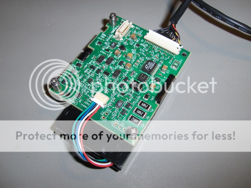
I found it easiest to use TI's software to modify the contents, sadly their software can't import bin files only txt files so I just saved their content as txt and filled in my hex content in the txt file instead and it worked perfect.

Picture above is original bin file.

And after modifying it looks like this, you can download the hex to txt file in my dropbox and import it in the Ti software.
Dropbox link

This is the new code.
What I do not understand is the value of the new battery hex FA60 which is 64096 in decimal. Orginal battery had a value of 04BF which is 1215 - Why is the new capacity 1800 not written as 0708 hex ?
Also why is MaxT DeltaT C0 hex which is 192 ?Leave a comment:
-
-
Re: Help identifying this chip - battery controller chip ?
The TI URL is now dead. I'm attaching the software.Leave a comment:
-
Re: Help identifying this chip - battery controller chip ?
Hehe that software was a good tip - if I can make it work it will simplify everything.Attached FilesLeave a comment:
-


-
 My question pertains to understanding the control circuity inside a Dell PT434 type battery used in Dell E6400, E6410 and other Dell notebooks?
Does anyone have a circuit diagram for the inside of a Dell PT434 battery and/or a description of how the control lines work to control this battery?
My reason for asking is I have a battery which I cannot get to charge beyond 1% in a Dell E6410 or E6400.
The LED bar graph charge indicator on the battery shows one LED lighted when the info button is pressed.
I have tried multiple different Dell power adapters. My Dell... -
 Hi
Hi
I have a very strange issue with the BIOS SPI chip of an ASRock B650M PRO RS motherboard.
The SPI chip is an Winbond 25Q256JWEQ model (1V8).
The motherbaord doas not POST - it lits only CPU and DRAM EZ Debug Leds, and stays that way forever.
The Flashback function of the motherbaord is also not working, despite all instructions followed correctly - I'm 100% sure of this.
I have then desoldered the chip, backupped the contents, and tried to earease the chip in order to program stock image, but the chip is locked by status registers SREG2 (TB) and SREG6... -
 Hello everyone,
Mark and model: ASUS X571
Symptoms: not turning on. There is only the LED battery indicator working. The owner of the laptop told me this problem arrived one week after having changed the battery. He then managed to power on the laptop only once, and then it never powered on again.
Tests already made:
- Battery is charging when laptop is plugged in. The LED battery indicator turns white after a couple of hours of charge, indicating that battery is fully charged. However, laptop won't turn on anyway, with or without AC plug.
- I have removed... -
 I bought a Vostro 3400 motherboard (LA-K033P) to upgrade over my damaged Inspiron 5593 (LA-J091P) board. Everything else is ok except for the battery. This battery I am using now is already a replacement one since I disposed of the bloated original one. Back in the Inspiron 5593 motherboard, the battery charges fine and is identified just fine. However, with the upgraded motherboard, suddenly the replacement battery is labeled as "Not a dell battery". When I borrow a similar battery from my colleague (which did not have replacements yet), it is identified and charges just fine.
... -
Hi ya folks,
I have this MacBook Pro A2485 (M1 Pro 2021) which came in for repair.
It had a shorted SSD power supply chip. Therefore it was stuck at 5V.
I replaced it and the SSD are fine. No more shorts.
But The mac still pulls 5V and 200mA. If i leave it alone for 5 mins, the mac manages to receive 20V and 40mA. Of course, which doesnt mean the mac starts after power meter reading 20V.
But while the mac is stuck at 5V, i checked the board with thermal and found this chip was trying to start. Chip picture is attached.
Chip marking...
Leave a comment: