Circuit voltage measurement problem.

Collapse
X
 
  • Time
  • Show
Clear All
new posts
  • link988
    Member
    • Aug 2011
    • 11

    #1

    Circuit voltage measurement problem.

    Hi

    I got an issue with power supply section of my plasma TV. When turned on it seem to get green light like its starting and after like 10 sec goes to blinking red.

    I opened up the unit and started pinpointing the culprit so found when TV just switched on at point where it supposed to be 400V to LLC_SUPPLY it goes up to 380V and decreases to about 140V then a relay click and blinking light appears voltages just gradually continues to drop. I traced it to bridge rectifier and got 230V on pin 2 when tv in that 10 sec period and goes to 0 when red light starts blinking. The question is on pin 3 is the Volatge supposed to be 230V as well, as arrows show that it is an input as well? (its probably me not understanding how to measure it maybe? I measured it the same way as pin 2. DMM to AC setting and black to good ground and red probe to pin 2 and pin 3)


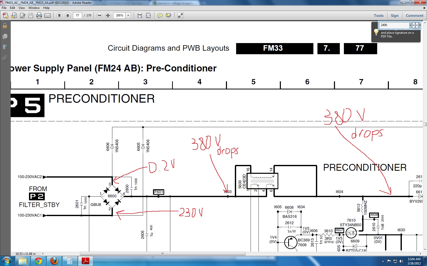
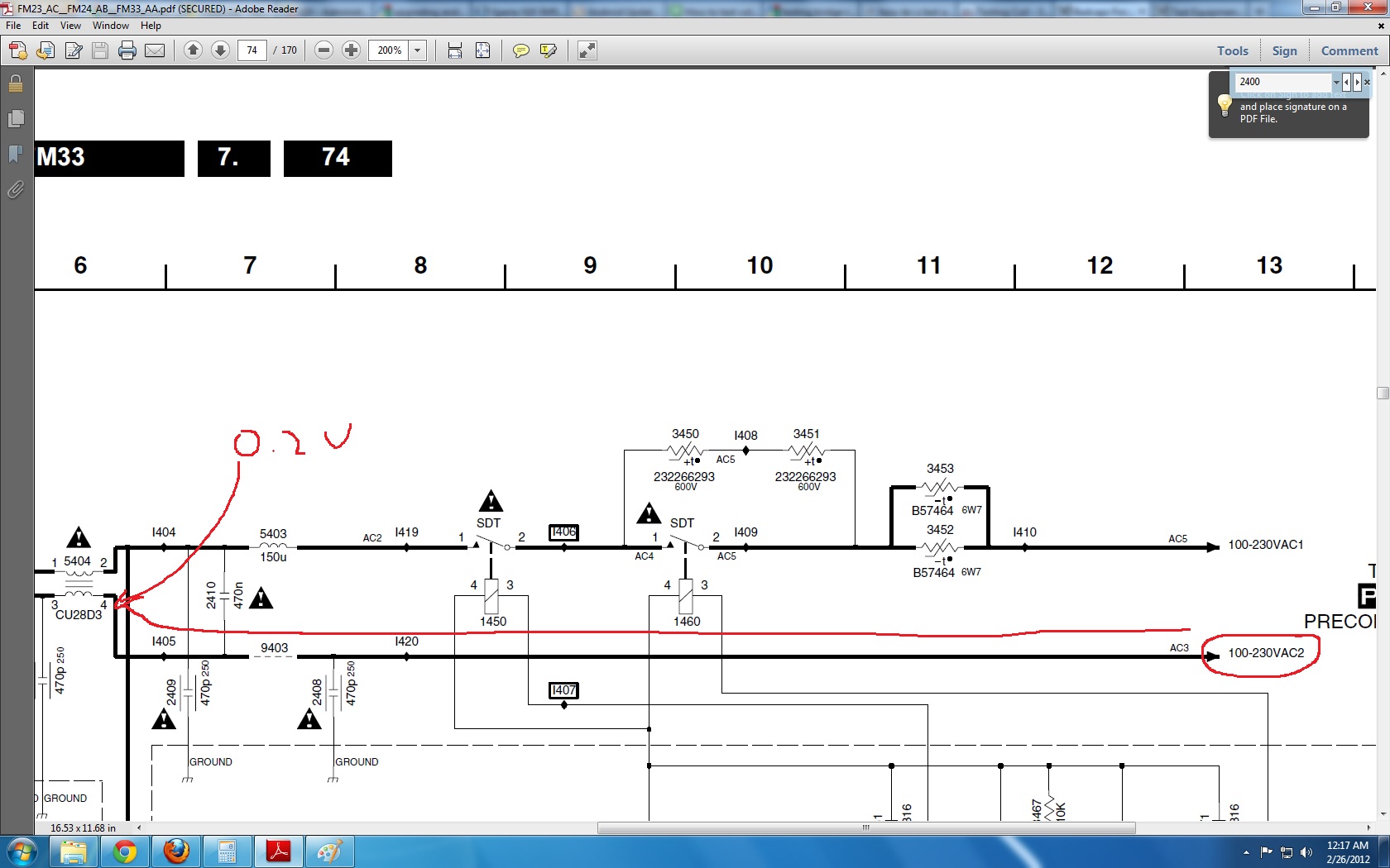
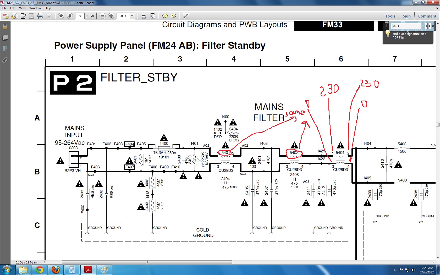
    Is that AC2 line supposed to be 0V or I am making very stupid mistake when measuring it? Any help or advice please

    Thank you.
    Attached Files
  • retiredcaps
    Badcaps Legend
    • Apr 2010
    • 9271

    #2
    Re: Circuit voltage measurement problem.

    Originally posted by link988
    DMM to AC setting and black to good ground and red probe to pin 2 and pin 3)
    When measuring voltage at a bridge rectifier, you want to measure DC voltage.

    Remember what a bridge rectifier is supposed to do.
    --- begin sig file ---

    If you are new to this forum, we can help a lot more if you please post clear focused pictures (max resolution 2000x2000 and 2MB) of your boards using the manage attachments button so they are hosted here. Information and picture clarity compositions should look like this post.

    We respectfully ask that you make some time and effort to read some of the guides available for basic troubleshooting. After you have read through them, then ask clarification questions or report your findings.

    Please do not post inline and offsite as they slow down the loading of pages.

    --- end sig file ---

    Comment

    • link988
      Member
      • Aug 2011
      • 11

      #3
      Re: Circuit voltage measurement problem.

      Originally posted by retiredcaps
      When measuring voltage at a bridge rectifier, you want to measure DC voltage.

      Remember what a bridge rectifier is supposed to do.
      Thank a lot for reply.

      I measured the voltage at pin 4 which supposed to be output pin i think and pin 1 and both show 139 to 137 V variation untill TV starts the blinking light thing which I think is protection mode of some kind as relay clicks and voltage in rectifyer drops.

      If input is 232 V AC and output 137 -139 V DC does it mean rectifyer is done for? Or I should look around for defective components around it?

      Still curious why does AC1 reads normal 230V and the parallel to it reads 0 V can it be the cause of low output of rectifier?

      Comment

      • b700029
        Banned
        • Sep 2010
        • 640

        #4
        Re: Circuit voltage measurement problem.

        Take your measurements relative to the - pin on the rectifier (i.e. put black probe of DMM on it.) The + pin should give approximately 1.4 times your line voltage (~340V for 240V mains, ~170V for 120V mains.)

        You can also remove the rectifier and check its 4 diodes separately out-of-circuit.

        Comment

        • link988
          Member
          • Aug 2011
          • 11

          #5
          Re: Circuit voltage measurement problem.

          Originally posted by b700029
          Take your measurements relative to the - pin on the rectifier (i.e. put black probe of DMM on it.) The + pin should give approximately 1.4 times your line voltage (~340V for 240V mains, ~170V for 120V mains.)

          You can also remove the rectifier and check its 4 diodes separately out-of-circuit.
          Ah ok thanks just did it, and it measures to 298 - 300V and if its 1.4 x V AC then should be 322V aprox so its 20V off is that acceptable?

          What could cause the power to spike up to 380V DC operating voltage and then gradually drop to 140V over about 10 sec period?

          Comment

          • link988
            Member
            • Aug 2011
            • 11

            #6
            Re: Circuit voltage measurement problem.

            I found on another forum that graduall drop of voltage is highly likely caused by bad capacitors. So I just had a look around the diagram and its just a guess by could this 2 cpacitors be going bad and thus the whole thing is occuring? (Circled in Red). The caps look all right but that is all I can say about them.


            My guess is that TV starts (well no screen no sound but still) green light on then a voltage drop started and when it gets to about 140V the system detects a fault causing it to go into protection mode.
            Attached Files

            Comment

            • budm
              Badcaps Legend
              • Feb 2010
              • 40746
              • USA

              #7
              Re: Circuit voltage measurement problem.

              Well that pre-conditoner circuits is PFC Voltage booster to get the TV to run as close as possible as PF of 1, measure the DC the 400vdc caps when the TV is off, then the voltage should kick to close to 400Vdc when PFC circuits kicks in, but if there are problems, the PFC will shutdown, that is why you see DC on the 400Vdc caps goes down. Plasma use a lot of power as it is, and without PFC, it will be worst and consume more power.
              Never stop learning
              Basic LCD TV and Monitor troubleshooting guides.
              http://www.badcaps.net/forum/showthr...956#post305956

              Voltage Regulator (LDO) testing:
              http://www.badcaps.net/forum/showthr...999#post300999

              Inverter testing using old CFL:
              http://www.badcaps.net/forum/showthr...er+testing+cfl

              Tear down pictures : Hit the ">" Show Albums and stories" on the left side
              http://s807.photobucket.com/user/budm/library/

              TV Factory reset codes listing:
              http://www.badcaps.net/forum/showthread.php?t=24809

              Comment

              Related Topics

              Collapse

              • mkdj
                MacBook Air A2337 (820-02016) - 5V, won't turn on - please help me understand why
                by mkdj
                Hello everyone,

                About me, my goal and the equipment I (don't) have:
                I am brand new to this forum, and I am eager to learn about repairing laptops. I have an engineer background although I haven't done electronics for a while. I have watched several Youtube videos in the last two months, trying to understand how to diagnose a faulty motherboard. I have a USB-C Amp meter and a classic multi meter. No DC Power Supply to inject voltage, no soldering iron to replace components.

                About my issue and my goal:
                A friend of mine has a MacBook Air M1 A2337 that does not...
                04-03-2025, 08:28 AM
              • brispuss
                Ryobi 36V (aka 40V) 6Ah Faulty Battery Pack
                by brispuss
                Purchased a Ryobi 36V 6Ah battery pack maybe just over a year ago.

                Battery pack had been used on about 3 or 4 occasions for powering a cordless lawnmower. I was wanting to use this battery pack again recently, but on checking the battery charge state via the battery pack test button, there was no LED indication at all of charge state which suggested the pack was fully discharged.

                I found this to be odd as I usually fully recharge battery packs shortly after use. So either the pack developed some sort of fault which completely discharged the pack cells (after recharging),...
                12-28-2022, 02:58 AM
              • tvguy12012012120
                Zombie Samsung UN55NU6900F dead / no standby voltage - randomly came to life after hours of troubleshooting then died
                by tvguy12012012120
                This is my first attempt at troubleshooting a board like this, I know I could just buy a new board but I'm curious to figure out how this works. I've been testing different components in the evenings this week and I think the problem is with the IC failing to start up for some reason. When the board is plugged in there is no standby voltage.

                Then today it randomly sprung to life like a zombie but shortly died thereafter. I have no idea why it would have done that and its the first time I've seen it running. I discharged capacitors on the board last night, then it was sitting today....
                02-07-2025, 05:13 PM
              • jajo17
                HP Probook 470 G2 - white blinking - ADP_SIGNAL ?
                by jajo17
                Hello, I have this laptop with a bad motherboard. The LED in the socket is blinking white, endless loop. According to the information I found on the internet, this can be caused by several reasons that I am currently investigating.
                1. Damaged BIOS chip - it seems to be fine, CH341a programmer can read it
                2. BIOS RTC voltage shorted to ground - it seems to be fine, around 3V
                3. Damaged adapter identification circuit - I think there is a problem here, but please help explain the function
                What should be the voltage on ADP_SIGNAL when using a 65W HP adapter? My calculation of the voltage divider comes...
                02-28-2025, 05:18 AM
              • sam_sam_sam
                AE20218 Milliohm Meter Kit, 0.1 Milliohm Resolution, Four Wire Measurements bought one
                by sam_sam_sam
                I have been in need of a mega ohm meter for a while but just could not make up my mind to which one I want to buy and this one has a couple of things going for it can also be used on a computer to display a resistance graph plus it is a kit that you put together supposedly the only parts installed are the surface mount components

                I will probably make a rechargeable battery pack for so it can be used as a portable device and anywhere

                I kind a wish that it had a higher resistance value higher than 240 ohms at 10 milliamperes on high range but it is what it it
                On the...
                03-15-2025, 05:10 PM
              • Loading...
              • No more items.
              Working...