Announcement

Collapse
No announcement yet.

Philips 40PFL7007T/12 debug and repair. Fusion chip or PSU?

Collapse
X
 
  • Filter
  • Time
  • Show
Clear All
new posts

    Philips 40PFL7007T/12 debug and repair. Fusion chip or PSU?

    Hello everyone,

    I've got a Philips 40PFL7007T/12 TV and it died spontaneously. Didn't go intermittent, just one day it wouldn't turn on (about a year ago, actually, but sometimes it takes a while to get around to opening things up!). This isn't really my world, so apologies if I've messed up on terminology or not provided anything important - happy to be corrected.

    Oddly, it doesn't seem to do a lot of the things other people on the forum get from their faulty Philips/TPVision TVs - notably I don't get any Blink Codes or really any sign it's alive at all. I've sat staring at the standby LEDs for 3 minutes after power on to be sure I didn't miss them, and tried a few other things described below. Can someone confirm that with these TVs, once they start blinking, they keep blinking until they're unplugged?

    Diagnostics:

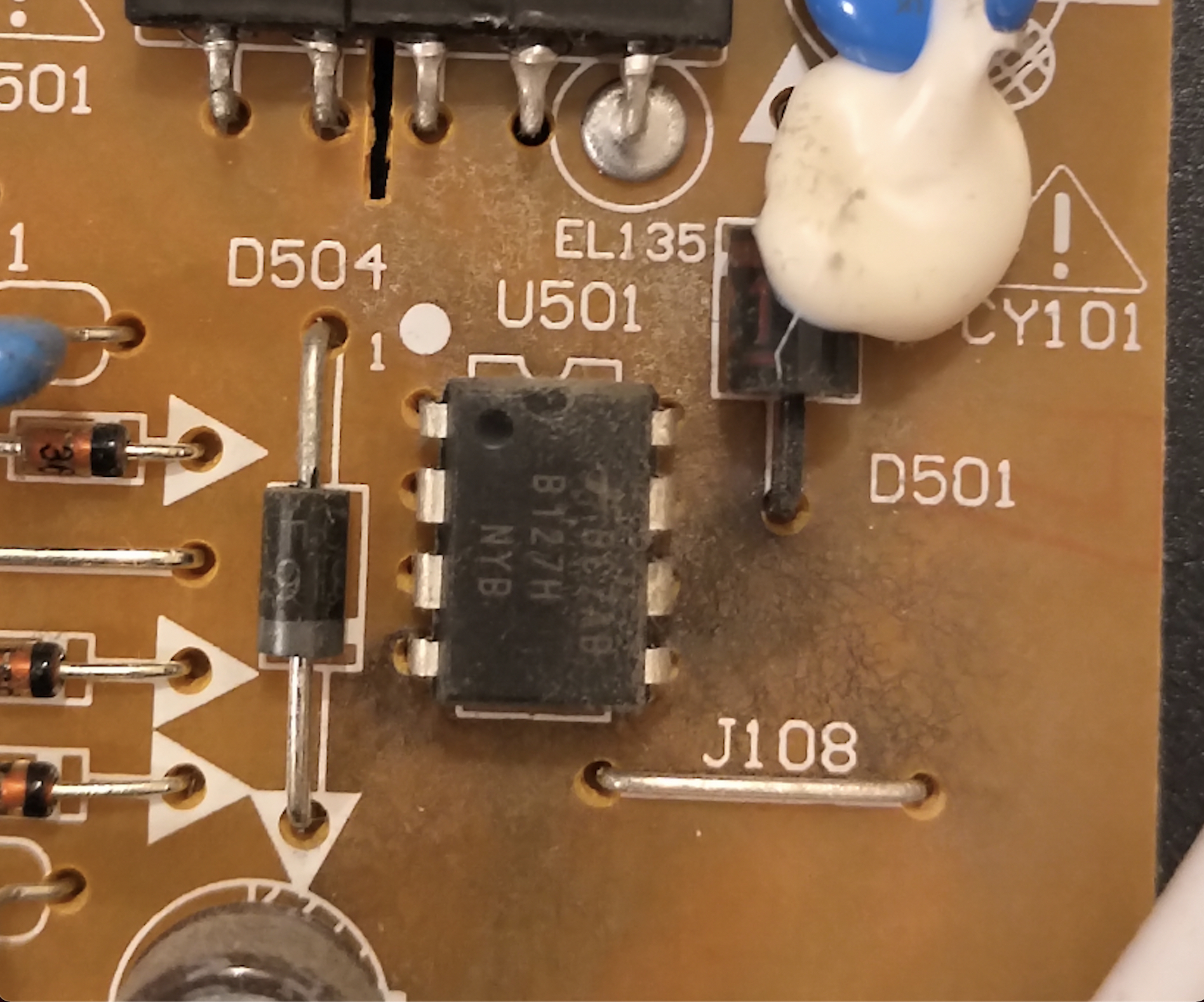
    I've opened it up today and probed some of the signals to see if I could identify what is wrong. I initially suspected the power supply because the failure appears so absolute, and when I got inside there was blackening on the PSU board around U501 and D501 which looked suspicious, as U501 is a (I think!) B127H which seems key to the SMPS…


    However, I'm not sure that's the issue as I can apparently get 12V out of the PSU...

    Probing signals on 1M95 (CN4), I see

    Code:
    1M95 voltages (reference to P3, GND1) with mains applied:
    
    1: 3.3
    2: 3.07
    3: GND/Ref
    4: 0
    5: 0.09
    6: 0.09
    7: 0.09
    8: 0.09
    9: 0
    10: 0
    11: 0
    12: 0
    13: 0.48
    14: 0.26
    Pressing the power button doesn't do anything, but if I ground P2 with a jumper, then I get the following:
    Code:
    1M95 voltages (reference to P3, GND1) while P2 is grounded
    1: 3.3
    2: <jumpered to GND>
    3: GND/Ref
    4: 0
    5: 12.41
    6: 12.42
    7: 12.42
    8: 12.42
    9: 0
    10: 0
    11: 0
    12: 0
    13: 3.2
    14: 1.4
    I wanted to get into one of the diagnostic modes, so I tried shorting the SDM solder blob on the main board to GND, but that makes no apparent difference. I also tried having them shorted while plugging the TV in (well, turning on at the wall). Also no dice. Not sure I have understood how to use this jumper right though. I waited for 2 minutes after doing this to be sure there were no blinks.

    After reading on this forum that these Fusion chips sometimes need re-balling, I also tried just… pressing... the heatsink down and plugging the TV in. Also no joy.

    I've also done some fairly boring things, like made sure the power button is working (but the TV used to come on as soon as you plugged it in, so that was really pointless).

    I'm surprised it's so dead that I don't get the LEDs blinking, but it looks like the standby MCU is on the main SoC so if it's BGA-related, perhaps the pins I've lost are taking out the MCU too? With the blackening around the B127H I'm wondering if there's some issue that also involved the PSU - could it be that it can deliver 12V until there's any real load and then it drops?

    My next steps if left alone would probably be something like:
    • Try to see whether at any point in startup the standby MCU is trying to pull the standby signal down to turn on the 12V supply (don't have a scope but could perhaps rig something up with an external MCU board)
    • Look to see if there are signals on the main board that get asserted during boot that I can probe to find out how far it's getting through the boot sequence.
    • Mess around with the Philips custom debug connection and see if I can just get a standard UART connection and dump some diagnostics...
    • Disconnect the main board and apply some external load to the 12V lines from the PSU and see that it can actually drive current.


    But before I sink more time into this I thought I'd see what you experts here suggest, even just knowing "it doesn't look like it's worth any more of your life!" would help

    Does anyone with experience with these Fusion SoCs have any advice for how I turn my speculation into something concrete and work out what might be going on?

    I don't have a toaster oven or other reflow capability, but I don't mind swapping out the board if that's a reasonable process and I can be sure it's just that main board - I can't tell for sure whether it's a clean swap or whether I'd need to do a bunch of re-flashing and provisioning. I am also not sure I can see any boards in stock, so maybe that's a problem too.

    All advice is welcome. I think I can get away with leaving this thing open for the next days at least so I can get some more measurements or try some other diagnostics if anyone suggests something.
    Attached Files

    #2
    Re: Philips 40PFL7007T/12 debug and repair. Fusion chip or PSU?

    could you show complete photo of the PSU and one close one on the CN4 printing label to know the name of the pins you listed above... or writing them here ..????

    Comment


      #3
      Re: Philips 40PFL7007T/12 debug and repair. Fusion chip or PSU?

      Thanks for the quick answer, sorry about the missing info.

      PSU:


      Main Board:
      (I took the chance to annotate what I did exactly when I said I'd shorted SDM to GND in case I messed that up)

      Detail for the pin allocation of the connector:

      Code:
      1: 3V3s : 3.3 
      2: STB : 3.07
      3: GND1: GND/Ref
      4: GND1: 0
      5: 12Vssb: 0.09
      6: 12Vssb: 0.09
      7: Vsnd : 0.09
      8: Vsnd : 0.09
      9: GND_S: 0
      10: GND_S: 0
      11: BLon: 0
      12: BL-DIM: 0
      13: BLIC: 0.48
      14: POK: 0.26
      (in case I've messed up the labelling, here's the source of truth)
      Attached Files

      Comment


        #4
        Re: Philips 40PFL7007T/12 debug and repair. Fusion chip or PSU?

        okay thanks for detailed upload.
        1- disconnect the main boards totally from the PSU .. then plug it in wall socket check on which pins on PSU you still have 3.3V

        Comment


          #5
          Re: Philips 40PFL7007T/12 debug and repair. Fusion chip or PSU?

          Does STB (PS-ON, ACTIVE LOW = Grounded turn on the power supply) change state when you turn TV on and off?
          U501 is the SMPS power supply for the 3.3Vstandby power supply.
          Last edited by budm; 12-28-2020, 05:11 PM.
          Never stop learning
          Basic LCD TV and Monitor troubleshooting guides.
          http://www.badcaps.net/forum/showthr...956#post305956

          Voltage Regulator (LDO) testing:
          http://www.badcaps.net/forum/showthr...999#post300999

          Inverter testing using old CFL:
          http://www.badcaps.net/forum/showthr...er+testing+cfl

          Tear down pictures : Hit the ">" Show Albums and stories" on the left side
          http://s807.photobucket.com/user/budm/library/

          TV Factory reset codes listing:
          http://www.badcaps.net/forum/showthread.php?t=24809

          Comment


            #6
            Re: Philips 40PFL7007T/12 debug and repair. Fusion chip or PSU?

            Originally posted by Diah View Post
            okay thanks for detailed upload.
            1- disconnect the main boards totally from the PSU .. then plug it in wall socket check on which pins on PSU you still have 3.3V
            Thanks, after disconnecting main board and plugging in, I get:

            Code:
            1M95 voltages (reference to P3, GND1) when fully disconnected from main board
            1: 3V3s : 3.3
            2: STB : 2.36
            3: GND1: GND/Ref
            4: GND1: 0.00
            5: 12Vssb: 0.00
            6: 12Vssb: 0.00
            7: Vsnd : 0.00
            8: Vsnd : 0.00
            9: GND_S: 0
            10: GND_S: 0
            11: BLon: 0
            12: BL-DIM: 0
            13: BLIC: 0.00
            14: POK: 0.00
            
            1M95 voltages (reference to P3, GND1) when fully disconnected from main board 
            AND P2 shorted to GND
            1: 3V3s : 3.3
            2: STB : <shorted to P3/GND>
            3: GND1: GND/Ref
            4: GND1: 0.00
            5: 12Vssb: 12.42
            6: 12Vssb: 12.42
            7: Vsnd : 12.42
            8: Vsnd : 12.42
            9: GND_S: 0
            10: GND_S: 0
            11: BLon: 0
            12: BL-DIM: 0
            13: BLIC: 0.00
            14: POK: 0.19
            Do you want me to check other locations on the PSU?

            Comment


              #7
              Re: Philips 40PFL7007T/12 debug and repair. Fusion chip or PSU?

              Originally posted by budm View Post
              Does STB (PS-ON, ACTIVE LOW = Grounded turn on the power supply) change state when you turn TV on and off?
              Just so I don't lead you up the garden path, I've understood this to mean "If you press the power button when the system is all plugged in as normal, does the state of the STB signal on the connector change?"

              A:
              ...not in any way I can catch with my multimeter... but holding the probes on STB and pushing the button, I see stable 3.07V on the STB pin...

              I also tried monitoring that pin while turning the machine on/off at the wall.

              Off-->On: ramp up to 3.07V (stable within ~1/2second)
              On-->off: --> decay back to 0V "slowly" - 10s to get below 0.1V

              Originally posted by budm View Post
              U501 is the SMPS power supply for the 3.3Vstandby power supply.
              Okay, so I guess it doesn't make sense for that to be the issue as we definitely seem to have 3.3V standby coming up right away.

              Is the level of blackening around it normal? Struck me as a bit odd, but this is the first TV I've had open...

              Comment


                #8
                Re: Philips 40PFL7007T/12 debug and repair. Fusion chip or PSU?

                Originally posted by mailforwho View Post
                Thanks, after disconnecting main board
                Do you want me to check other locations on the PSU?
                okay.. next test.
                before plugging the set to wall socket.... keep the main boards fully disconnected from PSU and make Jumpers :
                A- PIN 2 STB ---> GND
                B- with your DM peep tone option. test PIN 11 BLon to GND to check if you hear the peep tone as there short connection between this PIn 11 and GND.. if there are NO connection then do next step ---
                C- make jumper of 100 to 1000 Ohm resistor between PIN 1 3.3V and PIN 11 BLon then plug in the set to wall socket and check if yous LED Back light come on and stay on or it blinks once ON

                Comment


                  #9
                  Re: Philips 40PFL7007T/12 debug and repair. Fusion chip or PSU?

                  Originally posted by Diah View Post
                  okay.. next test.
                  before plugging the set to wall socket.... keep the main boards fully disconnected from PSU and make Jumpers :
                  A- PIN 2 STB ---> GND
                  B- with your DM peep tone option. test PIN 11 BLon to GND to check if you hear the peep tone as there short connection between this PIn 11 and GND.. if there are NO connection then do next step ---
                  C- make jumper of 100 to 1000 Ohm resistor between PIN 1 3.3V and PIN 11 BLon then plug in the set to wall socket and check if yous LED Back light come on and stay on or it blinks once ON
                  Thanks for the new steps.
                  Here's what I did
                  * remove all power
                  * disconnect main board from PSU (3 connectors, 1M54, 1M99, 1M95)
                  * Jumper P2 to P3 (GND) (jumper into female socket on disconnected end of connector)
                  * Test for continuity between P11 BLon and GND. --> no beep, ~90k when measured but looks dynamic (drifts down to 90K), so assuming this counts as no connection...
                  --> install jumper of 220R (all I have to hand, from a Kenwood Mixer repair kit!) from P11 to P1.
                  * Confirm jumper with multimeter, 0.2k
                  * Connect mains and power-on TV. No sign of backlight - either flicker or stable. I turned off the lights in the room to be sure I wasn't missing a flicker. If there is one, it's faster than I can see.
                  --> Measure voltage at P11, BLon: 3.2V (I think this confirms jumper OK)
                  --> Measure voltage at P5 (12VSSB) - 12.42V (think this confirms STB pulled down okay)

                  My jumper setup is attached.


                  Does this shed any light (sorry, couldn't resist) on the situation?

                  It looks like 1M54 (which I have disconnected) carries a series of "DIM" signals from the ssb to the PSU. Any chance I need to mess with BL-DIM too? I assume that's a secondary thing?
                  Jonny
                  Attached Files

                  Comment


                    #10
                    Re: Philips 40PFL7007T/12 debug and repair. Fusion chip or PSU?

                    you have edge BL. right? can you focus photo on the BL socket label ?
                    also you have label on PSU addressed the voltage of BL socket same way to the one goes to MB

                    Comment


                      #11
                      Re: Philips 40PFL7007T/12 debug and repair. Fusion chip or PSU?

                      ...I've also just probed P19 of the D-class amp, which I think is AUDIO-MUTEn (data sheet calls it (!PDN) (PDN, overlined, how should I denote that?) which is 'power down'.

                      These readings are while the board is plugged in and powered on (the 3V3s signal is present).

                      Initially: 0.49V.

                      If I then add the jumper between STB and GND (IE to fire up the 12V supply)

                      Pin 19 goes to 3.3V

                      Not sure if this is any relevance... but there you go

                      Comment


                        #12
                        Re: Philips 40PFL7007T/12 debug and repair. Fusion chip or PSU?

                        Originally posted by Diah View Post
                        you have edge BL. right?
                        Sorry, I don't understand all the questions... Is this about the nature of the panel? I honestly don't know. I'm pretty sure it's an LED backlight. I made sure to lift up the panel enough to see the front too - I think I'd see light leaking through the LCD even with the panel off?

                        Originally posted by Diah View Post
                        can you focus photo on the BL socket label ?
                        Yea, attached...


                        Originally posted by Diah View Post
                        also you have label on PSU addressed the voltage of BL socket same way to the one goes to MB
                        Again I'm afraid I'm not sure what the question is... I was taking measurements from the PSU side of the connector, and when I added the jumper to ground STB, I got the 12V supply in the right place, so I think I've got the connectors/pins the right way around. Is that what you meant?
                        Attached Files

                        Comment


                          #13
                          Re: Philips 40PFL7007T/12 debug and repair. Fusion chip or PSU?

                          you are correct at testing.. dont worry..lol
                          do you have 12Vssb on IM99 socket when you ground pin 2 on socket IM95?
                          i like to know if the PSU send 12VSSB or receive it from MB at socket IM99

                          Comment


                            #14
                            Re: Philips 40PFL7007T/12 debug and repair. Fusion chip or PSU?

                            Originally posted by Diah View Post
                            you are correct at testing.. dont worry..lol
                            do you have 12Vssb on IM99 socket when you ground pin 2 on socket IM95?
                            i like to know if the PSU send 12VSSB or receive it from MB at socket IM99
                            Thanks for sticking with it!

                            This is with the SSB still unplugged, right?

                            Taking measurements on 1M99 with main board (SSB) unplugged, and STB jumpered to ground

                            12Vssb: 12.42
                            GND1: 0.0
                            12Vssb: 12.42
                            GND1: 0.0
                            Val_bo: 12.42
                            GND_al_bo: 0.0
                            Val_bo: 12.42
                            GND_al_bo: 0.0

                            Comment


                              #15
                              Re: Philips 40PFL7007T/12 debug and repair. Fusion chip or PSU?

                              okay friend.. the end result. you need to take out the panel apart and keep it at safe place, same to the defuser sheets need to keep them at same order. yours set 40 its not much hard to access the BL. need to test them one by one not only as they lit ON but also test the build in ziner diode which forward the currents .. after you are sure 100% no issue at BL LEDs and all sockets joints solder okay.. you still can turn on the set on and it will turn on as well the BL with out panel in place.

                              after you reached the strips you can show me here to tell you the type and sepec of the led unit in case you need to replace..
                              this step important before you go to replace main boards. or backing it

                              Comment


                                #16
                                Re: Philips 40PFL7007T/12 debug and repair. Fusion chip or PSU?

                                Originally posted by Diah View Post
                                okay friend.. the end result. you need to take out the panel apart and keep it at safe place, same to the defuser sheets need to keep them at same order. yours set 40 its not much hard to access the BL. need to test them one by one not only as they lit ON but also test the build in ziner diode which forward the currents .. after you are sure 100% no issue at BL LEDs and all sockets joints solder okay.. you still can turn on the set on and it will turn on as well the BL with out panel in place.

                                after you reached the strips you can show me here to tell you the type and sepec of the led unit in case you need to replace..
                                this step important before you go to replace main boards. or backing it
                                Thanks for your help - what makes you suspect the backlight? As far as I can tell the BL is only turned on once the main MCU boots, not the standby MCU, but I don't see any sign the standby MCU is finishing boot because it should ground STB once it does to bring up everything else? Are there failures of the backlight that can take out the board in general?

                                Is taking out the panel/diffuser just so I can see the BL state?
                                Jonny

                                Comment


                                  #17
                                  Re: Philips 40PFL7007T/12 debug and repair. Fusion chip or PSU?

                                  Originally posted by mailforwho View Post
                                  Thanks for your help - what makes you suspect the backlight? As far as I can tell the BL is only turned on once the main MCU boots, not the standby MCU, but I don't see any sign the standby MCU is finishing boot because it should ground STB once it does to bring up everything else? Are there failures of the backlight that can take out the board in general?

                                  Is taking out the panel/diffuser just so I can see the BL state?
                                  Jonny
                                  in normal cases if we feed the BL ON with 3.3V as you tested before it will turn on with out main boards. the age of the TV. and from the LED BL socket you showed here.. its hard to make test from out side.. beside yours panel 40 its easy to take it apart.. after you remove it and other sheets you will have access to BL. i dont know what kind or type or how they are connected neither you... so left only to access to them. if any user over here had access on this model BL will be nice to tell here.. to me i didn't for this model .. but i faced many other Philips sets failed edge LED and they were newer than yours model.

                                  Comment


                                    #18
                                    Re: Philips 40PFL7007T/12 debug and repair. Fusion chip or PSU?

                                    Originally posted by Diah View Post
                                    in normal cases if we feed the BL ON with 3.3V as you tested before it will turn on with out main boards. the age of the TV. and from the LED BL socket you showed here.. its hard to make test from out side.. beside yours panel 40 its easy to take it apart.. after you remove it and other sheets you will have access to BL. i dont know what kind or type or how they are connected neither you... so left only to access to them. if any user over here had access on this model BL will be nice to tell here.. to me i didn't for this model .. but i faced many other Philips sets failed edge LED and they were newer than yours model.
                                    Looks like there's some info here:
                                    https://masterelectronicsrepair.blog...0pfl7007t.html

                                    I think this is the most helpful bit
                                    Main features of the PHILIPS 40PFL7007T device:
                                    Installed matrix (LED panel) LTA400HL15 code 003.
                                    To power the backlight LEDs, a converter is used, combined with a power supply unit, controlled by a PWM controller 0Z9909TN x 2, LM358G.
                                    https://www.panelook.com/LTA400HL15_...iew_16750.html is the panel.

                                    I'll have a look tomorrow and decide whether I'm going to brave the next steps!

                                    Comment


                                      #19
                                      Re: Philips 40PFL7007T/12 debug and repair. Fusion chip or PSU?

                                      "12: BL-DIM: 0" you need 1K resistor between BL-DIM and STBY 3.3V since the BL-DIM does not have pull-up resistor.
                                      Never stop learning
                                      Basic LCD TV and Monitor troubleshooting guides.
                                      http://www.badcaps.net/forum/showthr...956#post305956

                                      Voltage Regulator (LDO) testing:
                                      http://www.badcaps.net/forum/showthr...999#post300999

                                      Inverter testing using old CFL:
                                      http://www.badcaps.net/forum/showthr...er+testing+cfl

                                      Tear down pictures : Hit the ">" Show Albums and stories" on the left side
                                      http://s807.photobucket.com/user/budm/library/

                                      TV Factory reset codes listing:
                                      http://www.badcaps.net/forum/showthread.php?t=24809

                                      Comment


                                        #20
                                        Re: Philips 40PFL7007T/12 debug and repair. Fusion chip or PSU?

                                        you can also test. put back all sockets in place. read VDC on LED socket (CN2) pins L_CA & R_CA references to TV chassis.. power on and notice if there any activity on both pins.

                                        Comment

                                        Working...