Announcement

Collapse
No announcement yet.

Power supply build quality pictorial. part 2

Collapse
This is a sticky topic.
X
X
 
  • Filter
  • Time
  • Show
Clear All
new posts

    Re: Power supply build quality pictorial. part 2

    Originally posted by momaka View Post

    I'm also surprised only "350V" caps were used for the input. That's obviously cutting it a bit close, as a 230V AC line comes out to about 325V DC.
    We have 230V since 1997 before it was good old 220V.
    These capacitors are connected in series so they could handle the rectified ac even now.
    But most of the electrolytic caps have to go. Some measured so leaky and high esr that could be part of the many problem the unit has.

    Btw Line and Neutral are fused since there wasn't really a standard how the AC socket was wired.
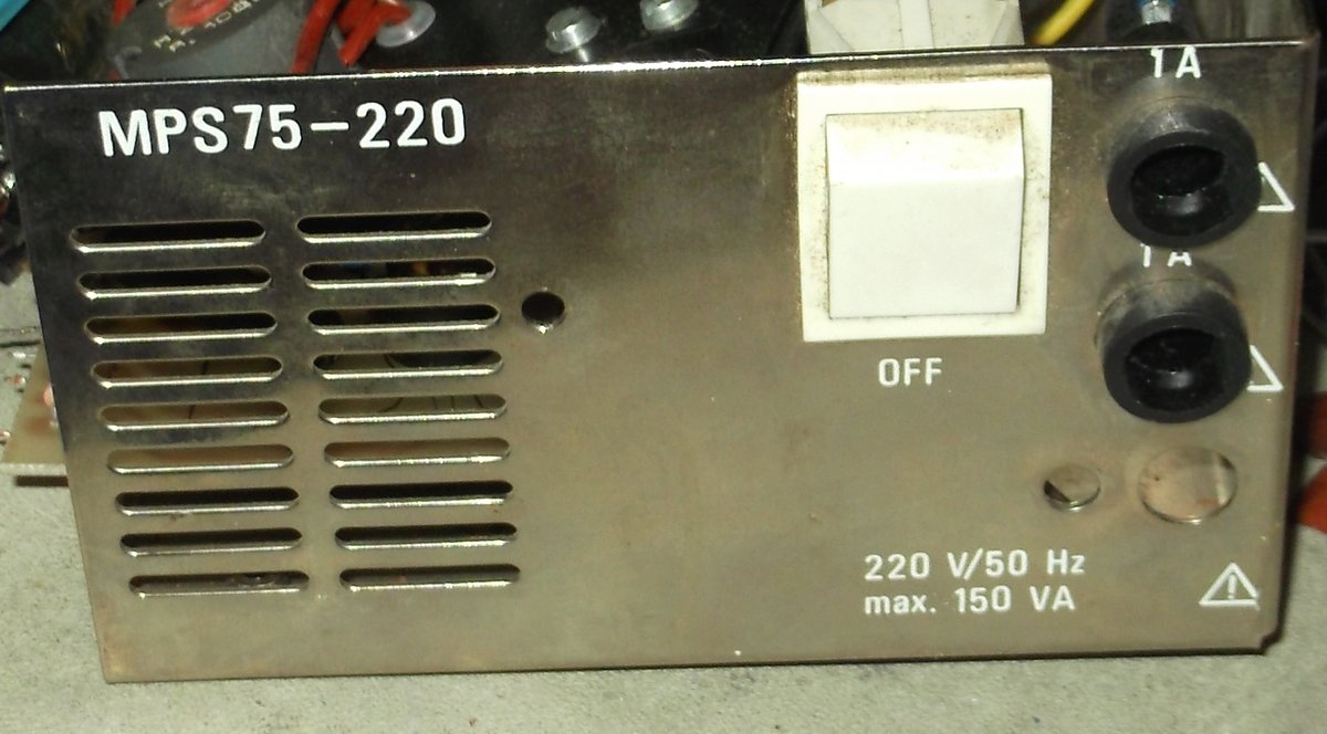

    Originally posted by PeteS in CA View Post
    Wow! That almost looks like it was hand built by a hobbyist!
    Check out how the primary of the main transformer is connected. That modification is all genuine factory condition!
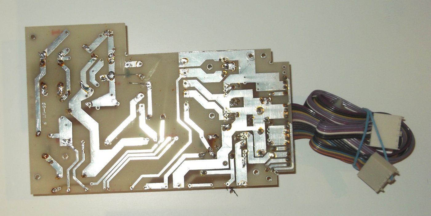

    Keep in mind that it's a 286 PC commie knockoff unit. Not something that was made on the US

    I might be able to contact the original engineer who worked on this model. I'm still trying to figure out some values of some foil capacitors and resistors. Markings have burned or peeled off...
    Attached Files

    Comment


      Re: Power supply build quality pictorial. part 2

      The 1980s? (and a chunk of the 1990s) (at least true for the early-1990s, which would be pre-NAFTA, IIRC) It would probably be from the USSR. Back then, imports from China were at least about as rare as a Lamborghini on a Vermont road!

      And "220 V", at least for the Americas, would most likely be an old transformer. I would expect 240 V over in the Americas for a later transformer, for "range and clothes dryer plugs".
      Last edited by RJARRRPCGP; 01-11-2019, 04:55 PM.
      ASRock B550 PG Velocita

      Ryzen 9 "Vermeer" 5900X

      32 GB G.Skill RipJaws V F4-3200C16D-32GVR

      Sapphire Nitro+ Radeon RX 6750 XT

      eVGA Supernova G3 750W

      Western Digital Black SN850 1TB NVMe SSD

      Alienware AW3423DWF OLED


      "¡Me encanta "Me Encanta o Enlistarlo con Hilary Farr!" -Mí mismo

      "There's nothing more unattractive than a chick smoking a cigarette" -Topcat

      "Today's lesson in pissivity comes in the form of a ziplock baggie full of GPU extension brackets & hardware that for the last ~3 years have been on my bench, always in my way, getting moved around constantly....and yesterday I found myself in need of them....and the bastards are now nowhere to be found! Motherfracker!!" -Topcat

      "did I see a chair fly? I think I did! Time for popcorn!" -ratdude747

      Comment


        Re: Power supply build quality pictorial. part 2

        Originally posted by pdavid View Post
        IMB PC compatible power supply from the late 80s Hungary.
        More pics pls!

        Comment


          Re: Power supply build quality pictorial. part 2

          Originally posted by momaka View Post
          Well folks, I did a nearly full recap on this PSU. All of the pertaining info can be found in this thread:
          https://www.badcaps.net/forum/showth...812#post861812


          Agreed.
          Given the system it was powering, though (a Dell Dimension E5150 with a "standard" 89W TDP Pentium 4 Prescott CPU), it was probably enough for what it is.

          As for the crap caps... they're gone now, for the most part.


          Well, I don't have a history of the PC it came out of, as it came from a repair shop that was scrapping this PC.

          But given the dust accumulation both inside the computer it was in and the PSU itself, I can say it probably provided at least 5 years of service. Also, the motherboard in that PC had nearly every KZG cap bulged, and the board was almost exclusively done with KZG. So it's possible these helped the PSU caps fail sooner. Of course, it could be the other way around too. I guess when dealing with crap cap brands, one can never tell "whodunit first" .

          Speaking of failed-with-no-visible-signs caps inside the PSU, here's an awesome collage of that (also shown in the recap thread above):
          https://www.badcaps.net/forum/attach...1&d=1541973750

          So now OST and Ltec are always on my remove-and-check (and likely recap) list when doing PSUs. I already had suspicions about the Ltec caps after recapping a 300W Delta PSU (where, again, I had a few "okay"-looking caps that turned out to be bad). CapXon is on that list too (except possibly for their KM series, since they always appear to bulge when they go bad).


          Allied/Deer/L&C did that on a lot of their PSUs. 100-Ohm 2W resistor on the 12V rail (1.44 Watts dissipation) will still run hot enough to discolor the PCB and output wires. You really want to go up to at least 270 Ohms to keep the dissipation at sane levels (around 0.5 Watts is okay). But I just removed that resistor altogether. Should be okay as long as the PSU is connected to a motherboard or there is some device to load down the 12V rail.


          And it probably doesn't get much airflow/ventilation from the fan.
          IIRC, KM was reported to be real bad, when it comes to failing while looking OK with your eyes! Possibly the worst when it comes to failing while looking OK!
          ASRock B550 PG Velocita

          Ryzen 9 "Vermeer" 5900X

          32 GB G.Skill RipJaws V F4-3200C16D-32GVR

          Sapphire Nitro+ Radeon RX 6750 XT

          eVGA Supernova G3 750W

          Western Digital Black SN850 1TB NVMe SSD

          Alienware AW3423DWF OLED


          "¡Me encanta "Me Encanta o Enlistarlo con Hilary Farr!" -Mí mismo

          "There's nothing more unattractive than a chick smoking a cigarette" -Topcat

          "Today's lesson in pissivity comes in the form of a ziplock baggie full of GPU extension brackets & hardware that for the last ~3 years have been on my bench, always in my way, getting moved around constantly....and yesterday I found myself in need of them....and the bastards are now nowhere to be found! Motherfracker!!" -Topcat

          "did I see a chair fly? I think I did! Time for popcorn!" -ratdude747

          Comment


            Re: Power supply build quality pictorial. part 2

            Originally posted by Stefan Payne View Post
            More pics pls!
            Date codes on parts are ranging between 83-89. Lots of Ukranian/Russian resistors. Inductors/magnetics, electrolytic capacitors are from Hungary. Back then the the COCOM list was in effect, so a lot of advanced western parts weren't allowed or quantity was limited to be imported to the USSR and it's allied states.

            I'm going to create a separate thread for this historical piece and about the restoration process. It's going to take some time.
            Attached Files

            Comment


              Astec AA12156 [IBM 6447192] AT power supply

              So I got five (5) old power supplies off of my local CraigsList in the summer. Owner said they were bad / failed bench testing many years ago. I still haven't tested any of them yet. But as with anything I get from CL, first I open it and clean it, to make sure there are no roaches or other pests. And with that, I also take pictures.

              For today's PSU, I have an old Astec AA12156 [IBM 6447192] power supply for you. Looks like mid-80's vintage – AT form factor (I think!) with the usual AT motherboard connectors, along with a few Molex and floppy drive connectors. There is also a big switch on the PSU case.
              https://www.badcaps.net/forum/attach...1&d=1547532390
              https://www.badcaps.net/forum/attach...1&d=1547532390
              https://www.badcaps.net/forum/attach...1&d=1547532390
              https://www.badcaps.net/forum/attach...1&d=1547532390

              … and a close-up of the label shot:
              https://www.badcaps.net/forum/attach...1&d=1547532390
              Adding up all the currents, looks like the 5V rail is rated for 15 Amps, the 12V rail for 4.2 Amps, the -12V rail for 250 mA, and the -5V rail for 300 mA. That adds up to 130.9 Watts total output. The label, however, doesn't say what the power supply is actually rated for, so I don't know if that's the real rating or not. Thus, let's see some pictures of the insides.

              Overall shot:
              https://www.badcaps.net/forum/attach...1&d=1547532390
              I like big CAPS and I cannot lie, you other brothers can't deny.
              Looks well built, I'd say. Besides the big caps, the main transformer is also quite chunky. Wires are all 18 AWG. There is also a dedicated input EMI/RFI filter board – something that Astec did on quite a few of their old PSUs.

              Picture of the input EMI/RFI filter board:
              https://www.badcaps.net/forum/attach...1&d=1547532390
              PCB suggests the design is from 1984. We have two fuses, a relay, two transformer-like components (I am going to guess these are the EMI/RFI common-mode chokes), and lots of PP film caps – some with safety logos, so probably X2 class. The double fuses suggest this unit might be double-pole fused (i.e. a fuse on both Live and Neutral). And I'm not sure if the relay is used just to bypass an NTC inrush current limiter / thermistor (which I don't even see.) or an automatic line voltage selection for 115V and 230V modes. I know Astec did the latter in some years later, like with the Astec PSU in my NetServer E-800 did (posted here a few pages back.) I don't see any Triacs, though, so maybe not.

              Next, a shot from the back… or is it the front?
              https://www.badcaps.net/forum/attach...1&d=1547532390
              Here you can see the capacitors a little better. Input has 4x Rubycon 200V, 440 uF caps (most likely wired as two sets of parallel caps in series for the voltage doubler – i.e. 440 uF total capacity at 400V.) Now that's some serious input capacitance! -Especially considering the low output ratings. But that's just Astec quality. The output filter capacitance seems equally serious, with a total of six (6!) United Chemicon SXA,16V, 2200 uF caps. Unfortunately, I couldn't get this unit opened fully, so I didn't trace how they are connected. Either way, I'm sure at least 3 or 4 of these are for the 5V rail, with the rest for the 12V rail. The -12V and -5V rail are probably filtered by the “smaller” capacitors behind them.

              As this shot shows…
              https://www.badcaps.net/forum/attach...1&d=1547532390
              … there is no toroidal inductor on the output after the main transformer, so this unit likely utilizes a flyback design. This would explain the large capacitors on the output. We also see two TO-220 components and one TO-247 component on the secondary heatsink. I couldn't read their numbers, but most likely the TO-247 is the 5V rectifier and one of the TO-220 components is the 12V rail rectifier. The third one I'm not sure about – could be a 7912 or a 7905 linear regulator for either the -12 or -5V rails, respectively (more likely a 7905.) But again, I couldn't get the main board out, so I couldn't read any of the part numbers. Same goes for the components on the small daughterboard on the secondary side - there is a 14 pin DIP chip on there that I'm not sure what it's for (I suppose this is the first time I make such detail-lacking post here. )

              Last but not least, a shot of the fan label:
              https://www.badcaps.net/forum/attach...1&d=1547532390
              It's a DC Pixie _PXDC12D4-90_, rated for 1.5 Watts @ 12V. Ball-bearing type and made in Japan. Appears to spin freely, though I have no idea if it works or not. Same goes for the rest of the PSU. As mentioned, the owner said these “failed bench tests” many years ago, but how he tested them, I didn't ask.

              Anyways, that is all. No PSU component breakdown for once.
              That said, if anyone knows anything more about this unit, feel free to post it. In the mean time, I'm going to move these PSUs into deep storage to await further testing. I know old AT PSUs need a good load on the 5V rail to be tested / work properly, and I don't quite have a proper load tester yet. So I won't be testing this PSU anytime soon. That being said, if anyone wants this PSU as-is for fixing up an old machine, just PM me.
              Attached Files

              Comment


                Re: Power supply build quality pictorial. part 2

                In case anyone thinks that all old PSUs were made well just like the above Astec... well, I don't think that's true. Here's a Leadman AT PSU I just posted in the Gutless & Fried thread, as I felt the unit belonged better in there (like any Leadman PSU, really ).
                Link to post here:
                https://www.badcaps.net/forum/showpo...postcount=1529

                Comment


                  Re: Power supply build quality pictorial. part 2

                  Back in 1979 or 1980 I saw a low performance knock-off of an older Boschert model. The performance was inferior, but the quality was better than the Leadman in that other thread. That thing is dangerous junk.
                  PeteS in CA

                  Power Supplies should be boring: No loud noises, no bright flashes, and no bad smells.
                  ****************************
                  To kill personal responsibility, initiative or success, punish it by taxing it. To encourage irresponsibility, improvidence, dependence and failure, reward it by subsidizing it.
                  ****************************

                  Comment


                    ALI LA 16 - MACOM [RL191 1-b] AT Power Supply

                    Another old PSU from the 5 non-working PSUs on Craigslist. I don't know if this one is AT or not and what it came out of or what it was used for. So if anyone has more info, please feel free to share it. Meanwhile, here are the pictures of the unit:
                    https://www.badcaps.net/forum/attach...1&d=1547939016
                    https://www.badcaps.net/forum/attach...1&d=1547939016

                    And here is a picture of the label:
                    https://www.badcaps.net/forum/attach...1&d=1547939016

                    I think it's a very old power supply, possibly even before AT standard (main frame or whatever it is called?), or perhaps just a custom-made unit for who-knows-what kind of computer. In any case, this unit does not have any standard output connectors aside from the two Molex drive ones. The thick 0 AWG red + black wires connect to the units 5V rail and ground, respectively. One set of the thinner wires has 12V and -12V, IIRC, and the other -5V and ground. As for the label – it doesn't say much regarding output power. And I'm not even sure if the “ALI LA 16 – MACOM” on the label is the model number or not. Anyhow, let's continue with the internal pictures.

                    Front cover removed, exposing the internal dual-PCB layout of the unit
                    https://www.badcaps.net/forum/attach...1&d=1547939016
                    The bottom board is the primary side and the top one the primary side.

                    To get the PSU taken apart, the PCBs slide out, leaving an empty metal shell
                    https://www.badcaps.net/forum/attach...1&d=1547939016
                    I don't know if this picture can give any prespective about the thickness of the metal used for the case… but I must say, this is the thickest sheet metal I have seen used for a PSU case – it's about twice as thick as that of any well-made PSU today, and very heavy. Clearly, we won't be dealing with a cheapo PSU here. I mean, take a look at the input connectors and their wiring too:
                    https://www.badcaps.net/forum/attach...1&d=1547939016
                    … properly color-coded, with removable clamps. Wire were 20 AWG, 600V, IIRC, which is probably okay for this unit.

                    Next, a shot of the primary-side input filter and protection components, sitting under a metal shield:
                    https://www.badcaps.net/forum/attach...1&d=1547939016

                    And here is the rest of the primary side:
                    https://www.badcaps.net/forum/attach...1&d=1547939016
                    We have two big Nichicon 200V, 680 uF caps, four diodes next to then (for the bridge rectifier) and two Aluminum heatsinks with the two switching transistors. Also note the 110V/220V jumper selector on the PCB. As for the two components with what appear to be short ferrite cylinder buttons… I have no idea what they are. MOVs? NTC thermistors (more likely)?

                    Speaking of the switching transistors…
                    https://www.badcaps.net/forum/attach...1&d=1547939016
                    … a pair of BUV47R NPN BJTs, rated for 9 Amps continuous… and [B]Made in Italy[b], it appears. If I had to guess, this unit uses half-bridge topology. The black “pyramid” component between the two BJTs is their driver transformer, also made in Italy! (Now, is anyone curious enough to call the telephone number listed on it? )

                    For anyone that wants to try and figure out all the questions above about the primary side, here is a PCB shot of the solder-side:
                    https://www.badcaps.net/forum/attach...1&d=1547939016
                    And in case the info written on the PCB is not too clear…
                    https://www.badcaps.net/forum/attach...1&d=1547939133
                    I am guessing that above is the PCB number (the “C1050 AL191/1-B”.) And again, we see another “MADE IN ITALY” label… so perhaps this PSU was all made in Italy, after all - nice!

                    Let's move onto the secondary side PCB.
                    https://www.badcaps.net/forum/attach...1&d=1547939133
                    Here, we see two transformers of some sort (one is probably just the output torroid), the output rectifiers and caps, and also some TO-92 components likely used for making the “logic” of the unit. Speaking of which, I don't see any ICs anywhere, so it must all be done with those TO-92 components. Most of them were just small transistors too, IIRC. Here's a closer picture of those “logic” components that are used to drive the primary-side transistors:
                    https://www.badcaps.net/forum/attach...1&d=1547939133

                    Next, the output rectifiers – old-school case-mounted diodes
                    https://www.badcaps.net/forum/attach...1&d=1547939133
                    https://www.badcaps.net/forum/attach...1&d=1547939133

                    And then the output filter caps:
                    https://www.badcaps.net/forum/attach...1&d=1547939133
                    Here we have a 6.3V 10000 (10k) uF and a 10V 2200 uF Nichicon 85°C general purpose caps for the 5V rail. The 12V rail is done by that single 16V 4700 uF blue vent-less Panasonic cap, IIRC, along with another smaller Panasonic cap. And the other caps are for the -12V and -5V rails, if I am not mistaken.

                    Here is a “front view” of that secondary side, particularly where the connectors are:
                    https://www.badcaps.net/forum/attach...1&d=1547939133
                    As you can see, the 5V rail has a steel… well, rail to accommodate for the output current. Same goes for the ground return path for that 5V rail. I assume the blue trim pot is for adjust the voltage? Another thing: the -12V and -5V rails are produced by a pair of 7912 and 7905 regulators, respectively. Also, when I looked at the secondary side, it appeared that the 4700 uF cap for the 12V rail was bulging from the bung. Moreover, the 10000 uF Nichicon cap for the 5V rail certainly had a slightly rounded vent. I tried pushing against it, but it was hard as a rock. So most likely that cap is/was starting to go bad at some point… or was it?

                    I was curious, so I pulled both the abovementioned caps and put them on my cheap ESR + capacitance meter after reforming for a minute @ 5V with a 10K series resistor. This is what I got:
                    https://www.badcaps.net/forum/attach...1&d=1547939133
                    https://www.badcaps.net/forum/attach...1&d=1547939133
                    Believe it or not, both of these caps are still in spec. The 4700 uF Panasonic is a bit high on capacitance, but still well within its 20% tolerance.

                    And finally, a shot of the secondary PCB's solder side:
                    https://www.badcaps.net/forum/attach...1&d=1547939133
                    Not much to say about it, as it looks rather neat. Again, we see “Copyright Olivetti” written on the PCB, so this must be some custom-made Italian PSU. Anyways, it looks pretty clean and well designed. However, there were a few cracked and under-soldered solder joints that I fixed. Perhaps this is what was wrong with the unit? I'll try to test it some day when I have more time and interest to dig into these old PSUs. Not sure if I'd have a user for anything this old either, but why not, right?

                    That said, if anyone has more info on this power supply, again, just feel free to post it here. Otherwise, that is all I have for now.
                    Attached Files

                    Comment


                      Re: Power supply build quality pictorial. part 2

                      And here is the rest of the primary side:
                      https://www.badcaps.net/forum/attach...1&d=1547939016
                      We have two big Nichicon 200V, 680 uF caps, four diodes next to then (for the bridge rectifier) and two Aluminum heatsinks with the two switching transistors. Also note the 110V/220V jumper selector on the PCB. As for the two components with what appear to be short ferrite cylinder buttons… I have no idea what they are. MOVs? NTC thermistors (more likely)?
                      I'm guessing inrush limiting thermistors.

                      Speaking of the switching transistors…
                      https://www.badcaps.net/forum/attach...1&d=1547939016
                      … a pair of BUV47R NPN BJTs, rated for 9 Amps continuous… and [B]Made in Italy[b], it appears.
                      SGS was an Italian semiconductor company that merged with the French company Thomson CSF in 1987 (several Thomson polyester caps can be seen in your pix). Modern name? ST Micro.

                      The SGS and Thomson CSF parts date that P/S to the 1980s, as do the DO-4 stud rectifiers (one of which may have a 1984 date code).
                      PeteS in CA

                      Power Supplies should be boring: No loud noises, no bright flashes, and no bad smells.
                      ****************************
                      To kill personal responsibility, initiative or success, punish it by taxing it. To encourage irresponsibility, improvidence, dependence and failure, reward it by subsidizing it.
                      ****************************

                      Comment


                        Re: Power supply build quality pictorial. part 2

                        Picked up an 8 bay eSATA box and just had to see what was inside. Surprisingly decent looking power supply for a consumer grade box. All the electrolytic capacitors are Chemicon KY capacitors. The X and Y caps are proper safety rated. Well defined clearance (and holes) between the high and low voltage sides.


                        Comment


                          Re: ALI LA 16 - MACOM [RL191 1-b] AT Power Supply

                          Originally posted by momaka View Post
                          Another old PSU from the 5 non-working PSUs on Craigslist. I don't know if this one is AT or not and what it came out of or what it was used for. So if anyone has more info, please feel free to share it
                          AT&T PC-6300/Olivetti M24/Xerox 6060. Being 110V, it's PC-6300 or Xerox 6060, probably a PC-6300 since those're the far more common one.

                          A bit of a funky computer design with two boards that connected together through the video card. Bottom of the chassis was the "motherboard" and top the ISA expansions. Even better, it had 16-bit expansion before IBM did. Predates 16-bit ISA, but a few cards were made for the 6300's interface.

                          Comment


                            Re: Power supply build quality pictorial. part 2

                            Did a search but didn't find this PSU anywhere in the thread. Worked for about 8 years before acting up. Opened it up and found swollen Teapos.

                            Worth fixing?
                            Attached Files

                            Comment


                              Re: Power supply build quality pictorial. part 2

                              Based on not a lot of info, I think it may be. The input filter looks like it uses safety agency rated capacitors, and I like the heavy metal, the hefty heatsinks. If the main transformer is as hefty as its part number suggests, the 700W rating may be in the realistic ballpark. That the PWM is a TL3845 is a good sign. The NCC PFC caps are nice ... so much so that the choice of Teapo for the output caps seems weird.
                              PeteS in CA

                              Power Supplies should be boring: No loud noises, no bright flashes, and no bad smells.
                              ****************************
                              To kill personal responsibility, initiative or success, punish it by taxing it. To encourage irresponsibility, improvidence, dependence and failure, reward it by subsidizing it.
                              ****************************

                              Comment


                                Re: ALI LA 16 - MACOM [RL191 1-b] AT Power Supply

                                Originally posted by Quagmire View Post
                                Did a search but didn't find this PSU anywhere in the thread. Worked for about 8 years before acting up. Opened it up and found swollen Teapos.

                                Worth fixing?
                                Going by the looks, it certainly seems better built than most average PSUs in the 700W range, even from known okay brands (like EVGA, Corsair, Antec, Thermaltake, etc.)

                                So yes, I definitely think it worth fixing / recapping.

                                Originally posted by Compgeke View Post
                                AT&T PC-6300/Olivetti M24/Xerox 6060. Being 110V, it's PC-6300 or Xerox 6060, probably a PC-6300 since those're the far more common one.
                                Oh wow, I didn't expect anyone to be able to pinpoint that kind of exact information. THANK YOU!

                                Originally posted by Compgeke View Post
                                A bit of a funky computer design with two boards that connected together through the video card. Bottom of the chassis was the "motherboard" and top the ISA expansions. Even better, it had 16-bit expansion before IBM did. Predates 16-bit ISA, but a few cards were made for the 6300's interface.
                                Interesting. I wonder then, if my PSU above has any value still. Maybe I should fix it (if it's broken) and put it up on eBay or something. Hopefully someone looking for one will find it a good home. I certainly don't have any PCs that are this vintage. Just one or two socket 7 boards at best.

                                Originally posted by PeteS in CA View Post
                                The SGS and Thomson CSF parts date that P/S to the 1980s, as do the DO-4 stud rectifiers (one of which may have a 1984 date code).
                                Yeah, as I didn't see a whole lot of micros and ICs in there (apart from the negative voltage regulators), that's what I was guessing about its vintage too - probably mid 80's or earlier design. Makes me wonder what's inside my dad's Sony TA-F70 stereo amp from the late 70's. It claims to be one of the first amps to use an SMPS (Sony calls it "Pulse Supply", or something along those lines.)
                                Last edited by momaka; 01-24-2019, 04:53 PM.

                                Comment


                                  Re: ALI LA 16 - MACOM [RL191 1-b] AT Power Supply

                                  Originally posted by PeteS in CA View Post
                                  Based on not a lot of info, I think it may be. The input filter looks like it uses safety agency rated capacitors, and I like the heavy metal, the hefty heatsinks. If the main transformer is as hefty as its part number suggests, the 700W rating may be in the realistic ballpark. That the PWM is a TL3845 is a good sign. The NCC PFC caps are nice ... so much so that the choice of Teapo for the output caps seems weird.

                                  Originally posted by momaka View Post
                                  Going by the looks, it certainly seems better built than most average PSUs in the 700W range, even from known okay brands (like EVGA, Corsair, Antec, Thermaltake, etc.)

                                  So yes, I definitely think it worth fixing / recapping.
                                  Thanks guys, I think I'll go ahead and try and re-cap it.

                                  The PSU certainly delivered the juice when I last had it in service; that PC was running an i5-750 oc'd to 4.0Ghz and two oc'd GTX285's in SLI. At the end, the machine would run fine for days with low to moderate loads but reboot itself whenever I started an intensive game or ran a benchmark.

                                  I pulled a few of the caps that were visibly bulged and easy to access; they're Teapo SC series. The damaged ones seem to be the 3300uf/10V ones. Unfortunately I made an oops: I pulled 5 caps (all from the same location) that appeared physically identical not realizing one was a 2200uf/16V. Now I'm not sure which position on the board it sat in. How bad is that?

                                  BTW, should I start a new thread for this project or ask for advice here?

                                  Comment


                                    Re: ALI LA 16 - MACOM [RL191 1-b] AT Power Supply

                                    Originally posted by Quagmire View Post
                                    I pulled 5 caps (all from the same location) that appeared physically identical not realizing one was a 2200uf/16V. Now I'm not sure which position on the board it sat in. How bad is that?

                                    BTW, should I start a new thread for this project or ask for advice here?
                                    If you have a multimeter, it should be pretty easy to figure out (you'll get low resistance between 12V rail / yellow wires on ATX connector and the positive side/hole wherever this cap was installed.)

                                    Start a new thread, post good pictures there, and list all of the caps you took out of the PSU and all of the caps that you're going to replace. List brand, series, capacitance, voltage, and size. That information should also come helpful for future reference, in case someone who has the same PSU and happens to stumble upon the thread.
                                    Last edited by momaka; 01-24-2019, 10:14 PM.

                                    Comment


                                      Re: ALI LA 16 - MACOM [RL191 1-b] AT Power Supply

                                      Thanks momaka, I'll start a new thread. You're right, may be a good reference for anyone with the same PSU.

                                      Comment


                                        PowerTech WK-6200dL3N1 200W ATX PSU [FSP 400-0000-096 PCB]

                                        Time to post the 4th unit from the 5 non-working PSUs I got from CL. This one is a PowerTech model WK-6200dL3N1 by FSP/Sparkle (PCB # 400-0000-096). Although it is an ATX PSU, its case isn't quite standard ATX format and has a 92 mm fan on top.
                                        https://www.badcaps.net/forum/attach...1&d=1549000964
                                        https://www.badcaps.net/forum/attach...1&d=1549000964

                                        Output connectors are the standard affair, of course: main 20-pin ATX, 4x Molex drive, and one or two floppy connectors (can't remember exactly) - nothing more and nothing less. All wires are 300V-rated and 18 AWG (except for floppy.)

                                        Label:
                                        https://www.badcaps.net/forum/attach...1&d=1549000964
                                        We see that the 5V rail has a pretty high minimum load of 2.5 Amps and is also rated for the most current relative to all the other rails. Thus, clearly we will be dealing with an old 5V-heavy ATX PSU here. Let's have a look inside.
                                        https://www.badcaps.net/forum/attach...1&d=1549000964
                                        https://www.badcaps.net/forum/attach...1&d=1549000964
                                        https://www.badcaps.net/forum/attach...1&d=1549000964
                                        Now this seems a lot more legit for 200 Watts, unlike the 250 Watt HEC PSU I just posted in the gutless thread.

                                        I think one of the first things that caught my attention when I opened the PSU was the 8-pin IC on the primary side.
                                        https://www.badcaps.net/forum/attach...1&d=1549000964
                                        It's a TOPSWITCH TOP210PF off-line switch IC. Typical application for these is 5VSB generation. But why I find it interesting is because PSUs of this time generally didn't use such an IC too often and many used the antiquated 2-transistor design instead. But with this PSU having 3 transformers, it was clear that its topology was half-bridge. Thus, without even looking at the numbers of that IC, I already knew what it was for… and I'm glad to see FSP making a 5VSB design that was ahead of the typical competition at the time.

                                        Other good signs to note about this PSU: it has full input filtering (including a receptacle filter made by Delta), a proper bridge rectifier, nice big Rubycon input caps, 35 mm core main transformer, and even a fan controller board. The only two things I am going to pick on are the Jamicon caps for the output filtering and… the 5VSB design. But wait, didn't I just praise the 5VSB design above? -Yes I did… until we look into the details. In particular, note that there is no optocoupler for the 5VSB. This means the 5VSB circuit is running “open-loop” and not actually regulating to any set voltage (likely outputting anywhere from 8-15V). To get a stable 5V output on the 5VSB, this PSU uses a 7805 linear regulator. Why FSP did this is beyond my explanation, as open-loop designs with a linear regulator tend to be inefficient at high loads (mostly heat dissipated by the 7805). Still, the fact that the 5VSB uses an off-line switch IC makes it a lot safer if something goes bad. I can't say the same about 2-transistor 5VSB circuits.

                                        Anyways, moving onto the secondary side… here you can see two of the three output rectifiers:
                                        https://www.badcaps.net/forum/attach...1&d=1549000964
                                        As you might imagine, the TO-247 part is for the 5V rail (30 Amp part) and the two TO-220 parts for the 3.3V and 12V rails (20 and 10 Amp parts, respectively).

                                        Now remember I said I got these units as “non-working”? The picture above actually shows one of the things wrong with this PSU. You see the issue? No? Then look at the orange ceramic cap just to the left of the center of the picture – there is a dark spot on it. Originally, I thought that was dust or dirt. But after cleaning the PSU from dust, I was pretty sure this cap was blown. I pulled it out and measured it. It read short-circuit. This cap is part of the snubber circuit for the 12V rail rectifier. Luckily, the series 7.5 Ohm resistor (next to it) was fine and not opened. I haven't checked the rest of the PSU for faults, but I think this is probably the only thing wrong with the PSU. While this shorted cap typically won't stop the PSU from powering on, I think it either screws up the regulation or allows massive voltage spikes to appear on the 12V rail, making whatever system is connected to it to become very unstable.

                                        Speaking of voltage spikes and noise, let's see the secondary-side filtering of this PSU:
                                        https://www.badcaps.net/forum/attach...1&d=1549000964
                                        We have a mix of 10 mm and 12.5 mm diameter caps filtering the output rails (which is always nice, IMO.) The output caps are all Jamicon TK series. Also note the 3.3V rail doesn't have a regular toroid filter, but rather a very large “PI” inductor. As for the 5V/12V output toroid, it appears large enough with a good number of turns – more than likely sufficient for 200 Watts and not likely to burn itself out like in that HEC PSU.

                                        Next, a solder-side shot:
                                        https://www.badcaps.net/forum/attach...1&d=1549000964
                                        It looks well laid-out and most of the solder joints are decent, apart from a few blobs on the secondary side. A closer look, however, revealed a potential problem:
                                        https://www.badcaps.net/forum/attach...1&d=1549000989
                                        One component lead was left out a bit too long and bent in such a way, that it was almost shorting to a neighboring solder joint. But apart from that, the overall soldering is decent enough. And here is the soldering on the PWM control PCB:
                                        https://www.badcaps.net/forum/attach...1&d=1549000989
                                        Not much to say about it, as it looks pretty clean and well-done.

                                        Finally, a picture for my fellow fan label fans.
                                        https://www.badcaps.net/forum/attach...1&d=1549000989
                                        We have a Jamicon 90 mm fan, rated for 200 mA @ 12V.

                                        And to finish the post, a component summary below:

                                        Primary Side

                                        * Input filtering: Delta 06GEEG3E inlet filter; 0.33 uF + 0.1 uF RIFA X2-class caps; 2x 4.7 nF MKF Y2-class caps; 1x common-mode + 1x single-mode choke
                                        * T5AL250V fuse, SCK-054 (?) NTC thermistor, 2x MOVs (across big input caps)
                                        * 405 bridge rectifier; 600V, 18 AWG input wires
                                        * input caps: 2x Rubycon USR 200V, 680 uF, 85°C, 22 x 46 mm (ø x h)
                                        * main PS: 2x 2SC2625 BJTs (half-bridge), 105K 250V P.P. coupling cap
                                        * 2x Jamicon TK 50V, 2.2 uF, 5 x 11 mm caps for BJT drive
                                        * main PS snubber network: RC-type with 47-Ohm, 3W resistor + 1 nF, 1 kV ceramic cap
                                        * transformer cores: 35 mm main, 16 mm 5VSB, 16 mm driver with OPP detection coil(?)
                                        1x Jamicon TK, 25V, 47 uF, 5 x 11 mm (5VSB startup cap)

                                        ICs
                                        * TOP210PF1 (5VSB generation) running open-loop (no optocoupler)
                                        * 7805 regulator (5VSB output regulator)
                                        * KA7500b (PWM controller) + LM393n (for protections… OVP?/UVP?/SCP)
                                        * LM358 (fan controller)

                                        Secondary Side
                                        3.3 V rail (mag-amp regulated):
                                        * SBL2040CT (TO-220) Schottky rectifier
                                        * 2x Jamicon TK, 10V, 3300 uF, 12.5 x 32 mm with PI coil
                                        * PI coil: 16 turns, 4 mm hollow core, 16 AWG

                                        5 V rail:
                                        * SBL3040PT (TO-247) Schottky rectifier
                                        * 1x Jamicon TK, 10V, 3300 uF, 12.5 x 32 mm before PI coil
                                        * 1x Jamicon TK, 16V, 1000 uF, 10 x 22 mm after PI coil
                                        * PI coil: 5.5 turn, 8 mm core, 12-14 AWG

                                        12 V rail:
                                        * BYQ28E200 (TO-220) Schottky rectifier
                                        * 1x Jamicon TK, 16V, 1000 uF, 10 x 22 mm and no PI coil

                                        -12 V rail:
                                        * 1-1.5 Amp diodes as rectifiers
                                        * 1x Jamicon TK, 16V, 47 uF, 5 x 11 mm after PI coil

                                        -5 V rail… same arrangement as -12V rail above

                                        5 VSB rail:
                                        * 1-1.5 Amp diode as a rectifier
                                        * 1x Jamicon TK, 10V, 330 uF, 8 x 13 mm before 7805 regulator
                                        * 1x Jamicon TK, 16V, 22 uF, 5 x 11 mm after 7805 regulator before PI coil
                                        * 1x Jamicon TK, 16V, 47 uF, 5 x 11 mm after 7805 regulator and PI coil

                                        Aux. Sec. (PWM controller power):
                                        * 1x Jamicon TK, 35V, 330 uF, 10 x 16 mm

                                        … end of post
                                        Attached Files

                                        Comment


                                          Re: Power supply build quality pictorial. part 2

                                          Well, the most recent date code I spotted in the pix was "9752", on the PCB. So this was built in early 1998. This is consistent with the .7A 5VSB rating.

                                          I do remember a Delta PSU that was in design in early 1999 that used, initially, an open loop Topswitch and a 7805. So that was not necessarily rare as a design approach. We had to change the 7805 to an LM317, because the 5VSB turned on too fast with the 7805. By using the LM317 we were able to use a cap across an adjustment resistor to slow the 5VSB rise time. The customer, Sun Microsystems, was concerned that too fast a rise time might damage CMOS gates in the relevant circuits.

                                          That is one beefy PSU! I might believe it good for 235W or 250W. Those 680uF input lytics must have resulted in an amazing hold-up time! The big usefulness limiter nowadays would be that 5VSB output current rating.
                                          PeteS in CA

                                          Power Supplies should be boring: No loud noises, no bright flashes, and no bad smells.
                                          ****************************
                                          To kill personal responsibility, initiative or success, punish it by taxing it. To encourage irresponsibility, improvidence, dependence and failure, reward it by subsidizing it.
                                          ****************************

                                          Comment

                                          Working...
                                          X