Announcement

Collapse
No announcement yet.

Deer DR-A300ATX rebuild - I need some help.

Collapse
X
 
  • Filter
  • Time
  • Show
Clear All
new posts

    Deer DR-A300ATX rebuild - I need some help.

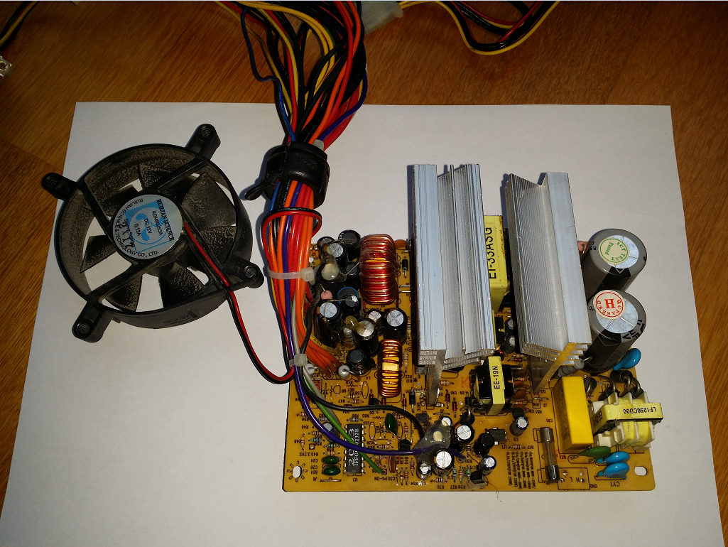
    So I have this Deer DR-A300ATX in a quite perfect shape that I rebuilt some time ago and want to rebuild it again.

    Here are the parts that I'd want to use:

    - TO247AB-case 13009 transistors (I initially wanted to use 20N60C3s in the same package but I only have one from an AIO PC's PSU)
    - brand new Samwha RD 2200uF 16v caps (they're big in diameter,btw)
    -MBR2045CT for 5v (20A 45V)
    -RFP50N06 for 12v (50A 60V - I guess it's okay to use 60V parts?)
    -MBR3045PT for 3.3v (30A 45v)
    -Yate Loon 8025H12 12V 0.18A - don't let the amperage fool you. I hooked it up once to 12v and the noise it does (it's greased, don't worry) rivalled an Delta!

    I want to make it more 12v heavy. The output toroid is very thick and most of the caps were replaced with Rubycon ZL and UCC KZE.

    All the parts come from an AIO PSU that I can only identify as "XEPEX E140166). It's pretty well built - GBU608 bridge rectifier, full input filtering with safety approved Y capacitors, ceramic fuse (might reuse that). Primary had a 82uF 450V Toshin Kogyo (TK, aka OST) LGW cap and secondaries were FULL of KZE and KY caps. Transformer is an EI33, and I guess they used that because the PSU is pretty small. (it was intended for an space that is half as tall as an normal PC PSU). Main PWM chip on that is an usual CM6800I.

    This is the PSU's heatsinks. (not my pic, it's from another thread from here since my phone's rear camera doesn't work)
    Attached Files
    Last edited by Dan81; 05-25-2017, 01:50 AM.
    Main rig:
    Gigabyte B75M-D3H
    Core i5-3470 3.60GHz
    Gigabyte Geforce GTX650 1GB GDDR5
    16GB DDR3-1600
    Samsung SH-224AB DVD-RW
    FSP Bluestorm II 500W (recapped)
    120GB ADATA + 2x Seagate Barracuda ES.2 ST31000340NS 1TB
    Delux MG760 case

    #2
    Re: Deer DR-A300ATX rebuild - I need some help.

    First off, 20N60C3 is a MOSFET made by Infineon. A 13009 is a very venerable (and good) bipolar transistor. Very different technologies, very different gate or base drive.

    Second, an RFP50N06 is a MOSFET, but you seem to intend to use it as a rectifier. And when you do try to select a schottky rectifier for the +12V output, you might be able to use a 100V part, but probably not a 60V part.

    Trying to boost its +12V current capability could get complex. Everything in the original design would have been sized to the orifinal current rating: the output transformer 12V winding, the rectifier, the output inductor winding, the PCB traces, the output harness wire gauge, the number and types of output connectors and pins. Replacing the rectifier with something beefier may be easy, rewinding the output inductor 12V winding with beefier wire is possible (MUST use same number of turns!), and you could reinforce the PCB traces. A beefier output harness and connectors could be pretty difficult, but you may be pretty much stuck with the main output transformer.

    Also, changing the balance of +5V and +12V output currents could screw up your regulation. That could be a 55 gallon drum of worms!
    Last edited by PeteS in CA; 05-25-2017, 10:57 AM.
    PeteS in CA

    Power Supplies should be boring: No loud noises, no bright flashes, and no bad smells.
    ****************************
    To kill personal responsibility, initiative or success, punish it by taxing it. To encourage irresponsibility, improvidence, dependence and failure, reward it by subsidizing it.
    ****************************

    Comment


      #3
      Re: Deer DR-A300ATX rebuild - I need some help.

      Originally posted by PeteS in CA View Post
      First off, 20N60C3 is a MOSFET made by Infineon. A 13009 is a very venerable (and good) bipolar transistor. Very different technologies, very different gate or base drive.

      Second, an RFP50N06 is a MOSFET, but you seem to intend to use it as a rectifier. And when you do try to select a schottky rectifier for the +12V output, you might be able to use a 100V part, but probably not a 60V part.

      Trying to boost its +12V current capability could get complex. Everything in the original design would have been sized to the orifinal current rating: the output transformer 12V winding, the rectifier, the output inductor winding, the PCB traces, the output harness wire gauge, the number and types of output connectors and pins. Replacing the rectifier with something beefier may be easy, rewinding the output inductor 12V winding with beefier wire is possible (MUST use same number of turns!), and you could reinforce the PCB traces. A beefier output harness and connectors could be pretty difficult, but you may be pretty much stuck with the main output transformer.

      Also, changing the balance of +5V and +12V output currents could screw up your regulation. That could be a 55 gallon drum of worms!
      I tested it with a Prescott 3GHZ HT Pentium 4 and it actually worked very nice. I just later noticed that RFP50N06 is a mosfet, because the PSU wouldn't turn on. I temporarily installed a SB1660CT and everything began working.

      I did some readings and it was pretty stable and almost spot-on: 5v was 5.01V, 12v was 12.11V and 3.3v was 3.32v.
      Main rig:
      Gigabyte B75M-D3H
      Core i5-3470 3.60GHz
      Gigabyte Geforce GTX650 1GB GDDR5
      16GB DDR3-1600
      Samsung SH-224AB DVD-RW
      FSP Bluestorm II 500W (recapped)
      120GB ADATA + 2x Seagate Barracuda ES.2 ST31000340NS 1TB
      Delux MG760 case

      Comment

      Working...
      X