Looking through my repair pictures and notes, it's been a long time since I posted anything in the LCD monitors section. So here goes that. 
I'm dedicating this thread to one of the very first LCD monitors I repaired (if not the first one), which was more than 10 years ago now. The monitor is a Wise Wing, model F199. It's a 19” CFL-backlit LCD. I got it for free off of Craigslist in 2009 from a guy, who said he bought it for cheap from Wallmart and the monitor worked only for a little less than 2 years before quitting.
When I saw the Craigslist post, I wasn't sure if the issue would be bad caps or not. Although I knew what they were and how to identify them, I was fairly new to BCN and recapping back then (started my electronics and PC repair journey around 2007-2008 or so.) But a 19” LCD back then was still considered decent for desktop use. And if nothing else, it seemed worth a shot at repairing, even if just for learning purposes.
So I got the monitor (and it seemed no one else was interested in it anyways.) This was it:
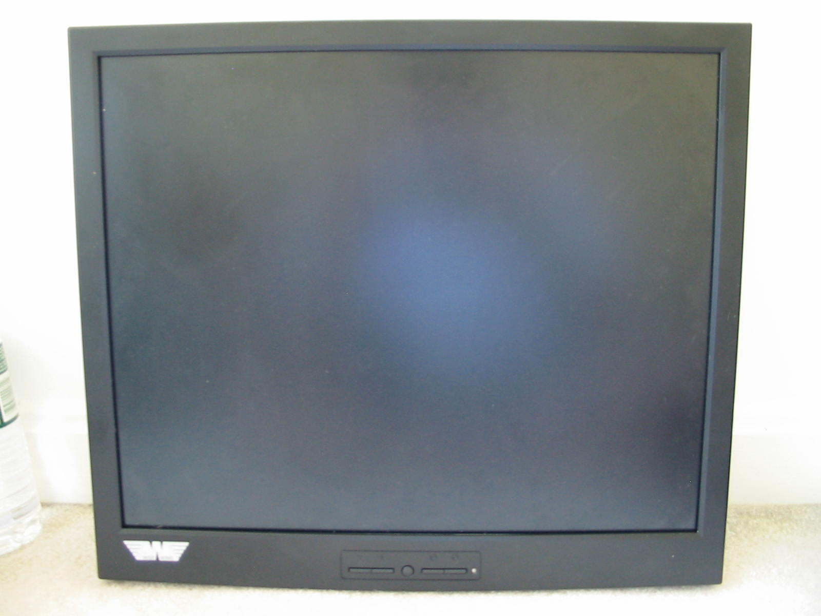
A classic “square” 5:4 ratio monitor. No stand was included (original owner had it on a custom mount, IIRC.)
I tested the monitor as-is first, and it just made a terrible high-pitched squealing noise. LED on front did not light up. So I tore it open (though, it looked like the original owner might have done that too before me, because there were some marks on the case possibly from tampering.)
LCD panel info:

Made by Chunghwa, model CLAA190EA. As I found out later throughout the years, Chunghwa is one of the cheaper manufacturers often used in “budget” and low-tier monitors. Between them and Chi Mei, though, I can't say which one is better (or should I say worse?)
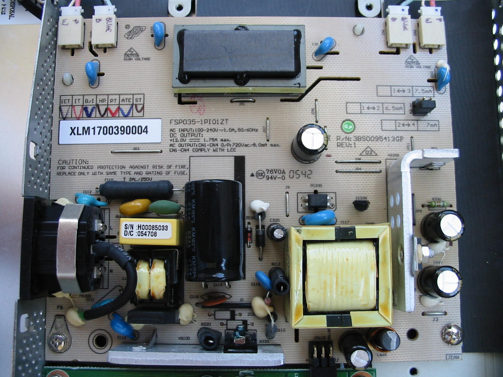
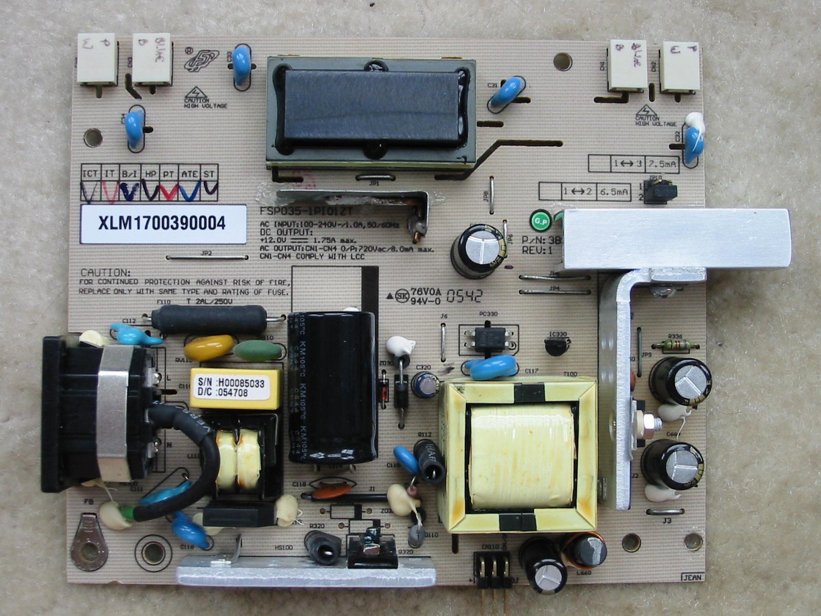
Unfortunately, I forgot to snap pictures of the monitor boards as I found it (I didn't document repairs as thoroughly as I do now.) But the power+inverter board in this monitor is an FPS035-1Pi01ZT, which seems to be a pretty popular board for bad caps. And of course, the issue on mine did turn out to be bad caps: 3x CapXon KF, 16V, 470 uF, 10 mm dia. and 1x CapXon KF, 16, 470(?) uF, 8 mm dia. - all obviously bulged. I replaced them with 3x Panasonic FM, 16V, 470 uF 10 mm dia. and 1x 16V, 470 uF, 8 mm dia.
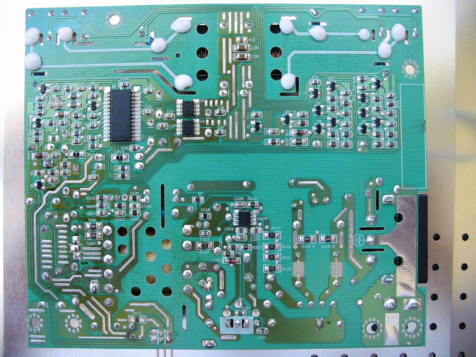
Here is a bottom (solder) side picture, just for component references possibly:
After this, I reinstalled back the PSU board, put on safety glasses, and plugged the monitor in the wall, half-expecting something to blow, as I had never done a recap before this (remember, this was me 10+ years ago .) Unsurprisingly, though, nothing blew up. Instead the monitor powered up and normally and displayed the usual message about lack of signal.
So I closed the case back up and put the monitor through a test session… with the monitor sitting on the ground and propped against the wall (due to not having a stand for it.) The monitor worked just fine. However, I noticed that even in a mildly warm room temperature, the case of the monitor on the back felt rather warm. I stripped the plastic case and ran it again for about an hour to see how hot it would get. I didn't have my type-K thermometer back then, but the metal case was getting pretty warm. This had nothing to do with the recap, but rather the PSU was probably just being pushed quite a bit in terms of its power rating and hence why it was running hot.
Thus, I decided to do a few modifications. First, I changed the “start-up” CapXon KM cap on the primary with a Panasonic FC (50V, 10 uF, 5x11 mm). Then, I put a bunch of holes on the metal back cover.
https://www.badcaps.net/forum/attach...1&d=1598287764
However, the monitor still appeared to run too warm for my tastes (and TBH, I've always been “a little” obsessed with keeping my electronic gear running cool – i.e. I always held the notion that if I couldn't put my hand on something, it's running too hot.) So for a while, I mothballed the monitor in storage while working on other projects and thinking of how to improve its cooling.
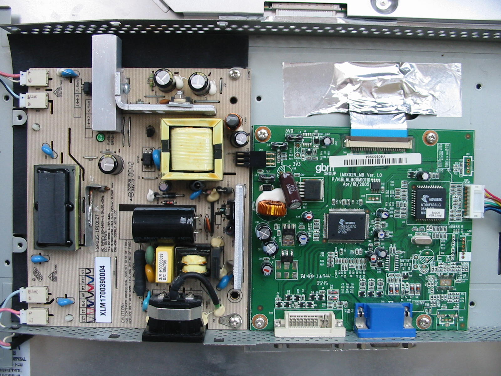
When I came back around it (some years later, since I kept using my CRTs), I found the hottest running parts on the power board were, unsurprisingly, the heatsinks. While thinking of how to increase the surface area of the two heatsinks, the logic board also caught my eye.
More CapXon!
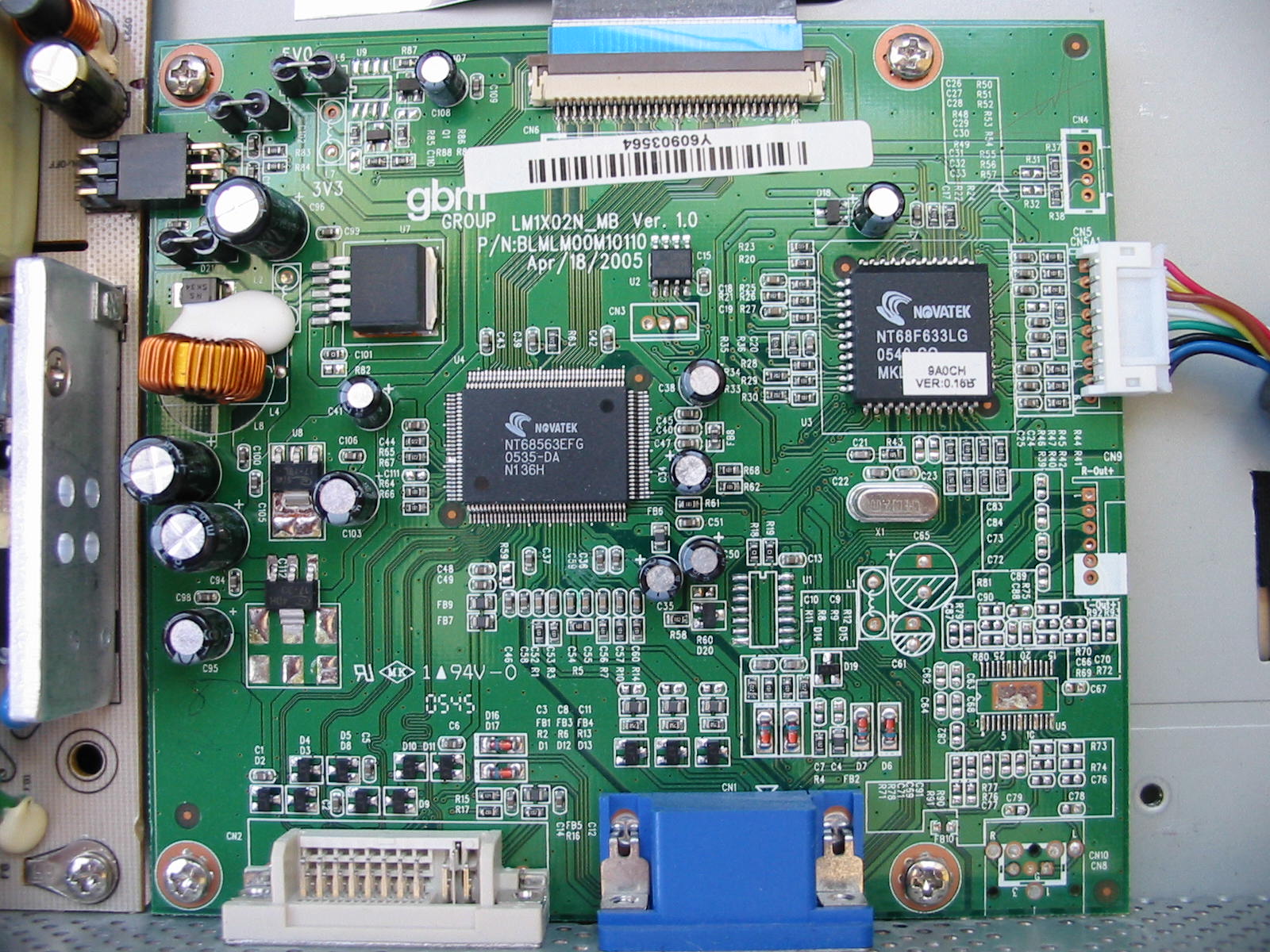
I don't remember if these were KM or KF series again, but more studying of the logic board showed that the toroidal inductor on the upper-left corner is part of a 12V to 5V buck converter. Having read how buck converters can fail sometimes if their caps went bad, I decided not to take any chances, so I recapped the input and output caps on it. IIRC, the input had a single CapXon (KM or KF), 16V, 470 uF cap, while the output had two CapXon (KM or KF) 16V caps (one 470 uF, and another 220 uF), along with a few smaller caps. I replaced the input and one of the output caps (the 220 uF one) with United Chemicon KZE, 16V, 680 uF and Nichicon HD, 10V, 470 uF, respectively.
https://www.badcaps.net/forum/attach...1&d=1598287764
https://www.badcaps.net/forum/attach...1&d=1598287764
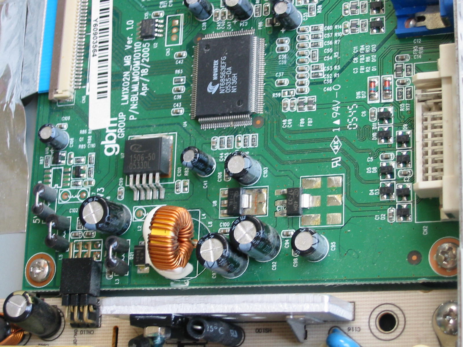
I didn't touch the smaller caps, because they were on the outputs of linear regulators (one of the linear regs is for 3.3V and the other for 1.8V, IIRC.) Instead, I soldered a few 4.7 uF SMD ceramics to the leads on the smaller caps. Figured that would be enough.
https://www.badcaps.net/forum/attach...1&d=1598287764
After this, I also came up with a plan for helping the PSU components to cool a little better.
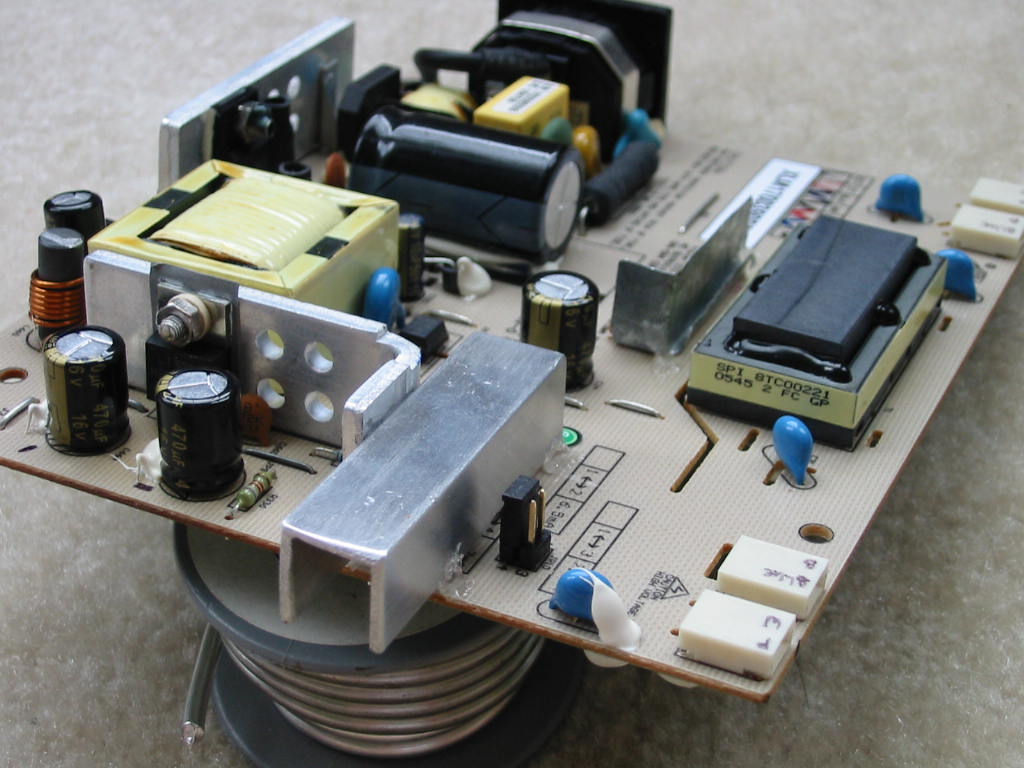
Basically, the secondary heatsink received a small extension to its surface area by bolting onto it (and coupling with thermal compound) a u-channel aluminum piece.
Meanwhile, I noticed that the inverter MOSFETs (U2 and U2) on the solder side of the PCB had their Drain pins tied together through small copper tracks and a jumper. Since many SMD MOSFETs usually recommend large copper tracks to connect to their Drain pins for better cooling, I soldered a “heatsink” (of sorts) to the jumper that connected the Drain copper tracks.
https://www.badcaps.net/forum/attach...1&d=1598288106
This is probably not the most effective solution, but it does help. The copper wire running across the steel sheet spreads the heat from the copper pads connected to the Drains on the MOSFETs, and the heatsink did actually appear to get as warm as the MOSFETs. I also used hot glue for extra “bracing”, just in case the heatsink somehow broke off or got loose. This probably wasn't the smartest idea, though, because as the monitor ran for its first 10-20 hours with these mods, the room did always end up smelling like someone had just plugged in a hot glue gun.
At this point in time, though, I had already acquired my type-K thermometer. After running the monitor again for a few hours then unplugging it, I stuck my type-K probe through the vents of the monitor and was rather shocked at how hot it ran: 55-65°C, depending on how far I slid the probe in. I think the highest I was able to measure was on a hot summer day (with room temperature close to 30°C): 69-71°C! No wonder those original CapXon caps died so quickly. This monitor is like a mini-oven inside. Heck, even the Panny FMs are bound to get a stressful workout at these temperatures (though being rated at 3000-4000 hours for the sizes of caps I used and assuming an average internal PSU temperature of 65°C, the FM caps should still last close to 6-8 years if used 24/7.)
I'm dedicating this thread to one of the very first LCD monitors I repaired (if not the first one), which was more than 10 years ago now. The monitor is a Wise Wing, model F199. It's a 19” CFL-backlit LCD. I got it for free off of Craigslist in 2009 from a guy, who said he bought it for cheap from Wallmart and the monitor worked only for a little less than 2 years before quitting.
When I saw the Craigslist post, I wasn't sure if the issue would be bad caps or not. Although I knew what they were and how to identify them, I was fairly new to BCN and recapping back then (started my electronics and PC repair journey around 2007-2008 or so.) But a 19” LCD back then was still considered decent for desktop use. And if nothing else, it seemed worth a shot at repairing, even if just for learning purposes.
So I got the monitor (and it seemed no one else was interested in it anyways.) This was it:
A classic “square” 5:4 ratio monitor. No stand was included (original owner had it on a custom mount, IIRC.)
I tested the monitor as-is first, and it just made a terrible high-pitched squealing noise. LED on front did not light up. So I tore it open (though, it looked like the original owner might have done that too before me, because there were some marks on the case possibly from tampering.)
LCD panel info:
Made by Chunghwa, model CLAA190EA. As I found out later throughout the years, Chunghwa is one of the cheaper manufacturers often used in “budget” and low-tier monitors. Between them and Chi Mei, though, I can't say which one is better (or should I say worse?)
Unfortunately, I forgot to snap pictures of the monitor boards as I found it (I didn't document repairs as thoroughly as I do now.) But the power+inverter board in this monitor is an FPS035-1Pi01ZT, which seems to be a pretty popular board for bad caps. And of course, the issue on mine did turn out to be bad caps: 3x CapXon KF, 16V, 470 uF, 10 mm dia. and 1x CapXon KF, 16, 470(?) uF, 8 mm dia. - all obviously bulged. I replaced them with 3x Panasonic FM, 16V, 470 uF 10 mm dia. and 1x 16V, 470 uF, 8 mm dia.
Here is a bottom (solder) side picture, just for component references possibly:
After this, I reinstalled back the PSU board, put on safety glasses, and plugged the monitor in the wall, half-expecting something to blow, as I had never done a recap before this (remember, this was me 10+ years ago
.) Unsurprisingly, though, nothing blew up. Instead the monitor powered up and normally and displayed the usual message about lack of signal. So I closed the case back up and put the monitor through a test session… with the monitor sitting on the ground and propped against the wall (due to not having a stand for it.) The monitor worked just fine. However, I noticed that even in a mildly warm room temperature, the case of the monitor on the back felt rather warm. I stripped the plastic case and ran it again for about an hour to see how hot it would get. I didn't have my type-K thermometer back then, but the metal case was getting pretty warm. This had nothing to do with the recap, but rather the PSU was probably just being pushed quite a bit in terms of its power rating and hence why it was running hot.
Thus, I decided to do a few modifications. First, I changed the “start-up” CapXon KM cap on the primary with a Panasonic FC (50V, 10 uF, 5x11 mm). Then, I put a bunch of holes on the metal back cover.
https://www.badcaps.net/forum/attach...1&d=1598287764
However, the monitor still appeared to run too warm for my tastes (and TBH, I've always been “a little” obsessed with keeping my electronic gear running cool – i.e. I always held the notion that if I couldn't put my hand on something, it's running too hot.) So for a while, I mothballed the monitor in storage while working on other projects and thinking of how to improve its cooling.
When I came back around it (some years later, since I kept using my CRTs), I found the hottest running parts on the power board were, unsurprisingly, the heatsinks. While thinking of how to increase the surface area of the two heatsinks, the logic board also caught my eye.
More CapXon!
I don't remember if these were KM or KF series again, but more studying of the logic board showed that the toroidal inductor on the upper-left corner is part of a 12V to 5V buck converter. Having read how buck converters can fail sometimes if their caps went bad, I decided not to take any chances, so I recapped the input and output caps on it. IIRC, the input had a single CapXon (KM or KF), 16V, 470 uF cap, while the output had two CapXon (KM or KF) 16V caps (one 470 uF, and another 220 uF), along with a few smaller caps. I replaced the input and one of the output caps (the 220 uF one) with United Chemicon KZE, 16V, 680 uF and Nichicon HD, 10V, 470 uF, respectively.
https://www.badcaps.net/forum/attach...1&d=1598287764
https://www.badcaps.net/forum/attach...1&d=1598287764
I didn't touch the smaller caps, because they were on the outputs of linear regulators (one of the linear regs is for 3.3V and the other for 1.8V, IIRC.) Instead, I soldered a few 4.7 uF SMD ceramics to the leads on the smaller caps. Figured that would be enough.
https://www.badcaps.net/forum/attach...1&d=1598287764
After this, I also came up with a plan for helping the PSU components to cool a little better.
Basically, the secondary heatsink received a small extension to its surface area by bolting onto it (and coupling with thermal compound) a u-channel aluminum piece.
Meanwhile, I noticed that the inverter MOSFETs (U2 and U2) on the solder side of the PCB had their Drain pins tied together through small copper tracks and a jumper. Since many SMD MOSFETs usually recommend large copper tracks to connect to their Drain pins for better cooling, I soldered a “heatsink” (of sorts) to the jumper that connected the Drain copper tracks.
https://www.badcaps.net/forum/attach...1&d=1598288106
This is probably not the most effective solution, but it does help. The copper wire running across the steel sheet spreads the heat from the copper pads connected to the Drains on the MOSFETs, and the heatsink did actually appear to get as warm as the MOSFETs. I also used hot glue for extra “bracing”, just in case the heatsink somehow broke off or got loose. This probably wasn't the smartest idea, though, because as the monitor ran for its first 10-20 hours with these mods, the room did always end up smelling like someone had just plugged in a hot glue gun.
At this point in time, though, I had already acquired my type-K thermometer. After running the monitor again for a few hours then unplugging it, I stuck my type-K probe through the vents of the monitor and was rather shocked at how hot it ran: 55-65°C, depending on how far I slid the probe in. I think the highest I was able to measure was on a hot summer day (with room temperature close to 30°C): 69-71°C!
No wonder those original CapXon caps died so quickly. This monitor is like a mini-oven inside. Heck, even the Panny FMs are bound to get a stressful workout at these temperatures (though being rated at 3000-4000 hours for the sizes of caps I used and assuming an average internal PSU temperature of 65°C, the FM caps should still last close to 6-8 years if used 24/7.)
Attached Files
if you find these attachements useful please consider making a small donation to the site

 : I live in a country with 120V AC line, so I don't technically need to use a 400V. A 200V cap would work just as well, provided I never move this monitor overseas or somewhere with 220/230/240V AC. With that in mind, I took a look through my junk bins, and found this good old Panasonic TSNH cap, rated for 200V and 150 uF.
 all the way.

Comment