
Hi everyone!
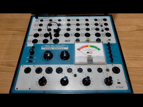
I managed to get my hands on a rough condition B&K 707 for "the best price" because it was not working. It's my first tube tester and I'm really wanting to get it up and running. I downloaded that manual that has the schematics and tested every resistor and capacitor and replaced the ones that failed. I replaced the missing 83 rectifier tube with a used but tested-good one. I also have a number 80 rectifier tube that I have used in tests before I found the 83 tube.
Initially I noticed that I was not getting the red on-light to turn on, but it would work when I applied pressure to the bulb behind it. I soldered component legs to the ground from the bulb brass and everything lights up now.
Here is the problem I am dealing with now:
Every calibration goes well and by the book, until it comes to calibrate the last and most important function. The Balance Control Adjustment. The needle in the gauge is vibrating. I don't think is should be doing that, right? I calibrated it anyway, with the 6M 10w resistor in pin 2 and 5 of socket 1, and adjusting the needle position using the pot closest to the transformer until the needle reads Zero while the Test 1 button is being pushed down.
When I test my one known bad tube, a 10DE7, the needle, on both Test 1 and Test 2, reads well into the Good range, with differences between the two readings. I have two NOS 12BA6 tubes and they peg the needle when tested. The needle is still vibrating on both tubes.
I just found another problem while writing this and checking things on the 707. I got a little tingle while lifting the chassis to double check the location of the Balance Control pot for this post. I took a measurement between the aluminum panel and Earth. It's reading almost 70V AC. That can't be normal.
Any advice?
https://www.youtube.com/shorts/wrVkbFtc_y8
https://www.youtube.com/shorts/1OGce5OGRDs


Comment