Announcement

Collapse
No announcement yet.

PSU component identification

Collapse
X
 
  • Filter
  • Time
  • Show
Clear All
new posts

    PSU component identification

    looking at the psu that cooked a mobo,


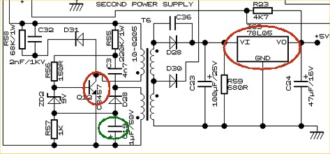
    have figured out that it must use "2-transistor" technology for the 5vsb.
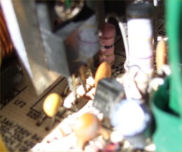
    one of these components (mofset?) is screwed to the Primary heatsink, and close to it is a small standard transistor, and right next to that, is a 3.3uf 50V cap

    anyway, here is an example diagram:
    have these 3 components being identified correctly (the 2 "transistors" and the critical cap)?


    Attached Files
    Last edited by socketa; 07-09-2014, 06:08 PM.

    #2
    Re: PSU component identification

    The 78L05 that is circled is the output regulator, on the output side of the circuit. It's not a transistor. OTOH, the 2SC3457 that is circled is the switch device.
    Last edited by PeteS in CA; 07-09-2014, 06:16 PM.
    PeteS in CA

    Power Supplies should be boring: No loud noises, no bright flashes, and no bad smells.
    ****************************
    To kill personal responsibility, initiative or success, punish it by taxing it. To encourage irresponsibility, improvidence, dependence and failure, reward it by subsidizing it.
    ****************************

    Comment


      #3
      Re: PSU component identification

      it cant be 78L05, if it was it would only give 100ma and not need a heatsink.
      even a 7805 is only 1amp.

      Comment


        #4
        Re: PSU component identification

        thanks for the reply
        but still none the wiser - as you might probably guess

        "The 78L05 that is circled is the output regulator, on the output side of the circuit. It's not a transistor. OTOH, the 2SC3457 that is circled is the switch device."

        that is why i put the phrase "2-transistor" in quotation marks - in case the phrase was used somewhat loosely

        where are these infamous "two transistors", and what do they do?
        i know that they are for voltage regulation (switches) to the 5VSB output

        all this is reasonably alien to me, but am slowly getting the hang of it

        so are all 3 components identified incorrectly?
        i traced the schematic back, and there is no other transistors (or mosfets, or PWM IC) between this section and the main input filtering and rectification.
        Last edited by socketa; 07-09-2014, 07:38 PM.

        Comment


          #5
          Re: PSU component identification

          try these

          what's the make & model of this brick anyway?
          got good foto's?
          Attached Files

          Comment


            #6
            Re: PSU component identification

            thanks
            here the pics:
            iso-450pp

            i've being told that this is a 2-transistor 5vsb with a critical cap.
            and the reason for this thread is that i would like to know where these particular 3 components are on this board

            1. where are these 2 transistors?
            2. where is the critical cap?

            (in case you are wondering - i've removed the bad caps,
            and am not interested in fixing it (have got other ones that i'm looking at re-capping))


            Attached Files
            Last edited by socketa; 07-10-2014, 12:28 AM.

            Comment


              #7
              Re: PSU component identification

              The 78l05 is not part of 5v Stand By circuit. It's a 5v 100mA max linear regulator, probably used to power the fan controller (if there's any) or the control circuitry on the secondary side.

              Go and look where the 5v sb cable from the atx connector goes, then follow the traces on the back of the pcb and you know how the 5v standby is generated.

              Comment


                #8
                Re: PSU component identification

                You should remove that voltage booster add on board that is located on the primary heatsink.

                Comment


                  #9
                  Re: PSU component identification

                  i think c21 and c22 are the 5v standby smoothers.

                  Comment


                    #10
                    Re: PSU component identification

                    "You should remove that voltage booster add on board that is located on the primary heatsink."
                    OK


                    traced back from the 5vsb cable, through a resistor, to a small transistor
                    top LH corner of the photo below


                    it goes to the LHS pin of that transistor
                    and the middle pin is 0 ohms back to the 5vsb connector output, although i can't see how.

                    anyway, it looks like this is one of the infamous "2-transistor" 5vsb transistors.
                    now, where is the other one?

                    so then,
                    is this page http://hardwareinsights.com/wp/how-a...-supply-works/ giving wrong information?, when it shows a photo of a "5vsb transistor" mounted on the primary heatsink, and then says directly underneath it:
                    "The 5vsb transistor as is actually part of a two-transistor circuit" then saying that it is this 2-transistor circuit that is replaced with pwm chip, and that it is these 2-transistor circuits that fail and destroy mobos

                    (ps, just realized that i cropped the example wring diagram on the RHS of that photo on post #1 - it's 5VSB, not 5V.
                    that diagram is from http://www.hardwaresecrets.com/artic...Supplies/327/2 )
                    Attached Files
                    Last edited by socketa; 07-10-2014, 06:45 PM.

                    Comment


                      #11
                      Re: PSU component identification

                      I have recapped and fan modded the same psu.
                      Attached Files

                      Comment


                        #12
                        Re: PSU component identification

                        There are topologies and topologies, designs and designs.

                        I'm not sure why you're stuck on this "2 transistor" issue. The power supply is new enough that it may not even use 2 transistors for 5v standby. later edit: and even if the 5v sb circuit is a two transistor circuit, that doesn't mean it must be the same circuit used by previous power supplies that used to fail sending high voltage to the motherboard. It is possible to make simple circuits that don't fail.

                        Hardware insights discusses ONE design, this power supply is maybe another design.

                        Anyway, I don't understand why you have this fascination with cropping pictures or making pictures that are 90% useless, because they're made from far away or they're cropped so much you can't look around the board to try to determine anything.

                        Don't you have a MACRO mode on your camera to get some better closeups?

                        Also, do you realize that - as far as I can tell - in all the pictures above and in all the posts you made there's NOTHING about the transistors/mosfets/rectifier diodes on the heatsinks?

                        Every picture you posted that's shot at a reasonable angle (let's say 45 degrees) the actual stuff is far away or you took the picture in such a way that I can't read any damn text on the chips.

                        See post 6 in this thread (your 3rd message here). Try to read what it says on any to-92, to-220, any IC in those pictures. If you can, I'll shut up.

                        How about you READ what's on the chips on heatsinks and write down here what it says. I'm not a wizard to guess what that power supply may use as a 5v sb circuit.

                        You finally started to follow that 5v sb circuit .. go with the trace until you hit a transistor or mosfet, read the code on it, search the datasheet to figure gate, source, drain pins or base/emitter/collector .. that should tell you which pin is the INPUT and which is the OUTPUT, so you can then further follow the trace on the pcb to whatever was before that transistor or mosfet.

                        I also don't understand what you refer to with the "top LH" or "LHS" ...
                        Last edited by mariushm; 07-10-2014, 07:17 PM.

                        Comment


                          #13
                          Re: PSU component identification

                          Originally posted by socketa View Post
                          where are these infamous "two transistors", and what do they do?
                          See this picture of yours for reference:
                          https://www.badcaps.net/forum/attach...1&d=1405036035
                          The main transistor (MOSFET) for the 5VSB is the TO-220 one mounted on the heat sink, right in front of the 5VSB transformer (the 5VSB transformer is the small one on the left with the "TISOS-EL16xxx marks). It's driven by that smaller TO-92 BJT transistor right in front of it. Looks like Q7 is the board designation for it. Has "H945" written on it. The optocoupler, U3(?), provides feedback how the 5VSB output voltage "is doing", and based on that changes the drive signal to Q7, which in turn changes for how long the TO-220 MOSFET turns on for.

                          The critical cap is that 3.3 uF, 50V cap right next to Q7. Some 2-transistor designs have it and others don't. When it goes bad, the voltage regulation on 5VSB can go out of control and send a really high voltage to the motherboard.
                          However, there is another scenario when the 5VSB circuit in this PSU can wreak havoc even if this cap didn't fail...

                          Originally posted by socketa View Post
                          in case you are wondering - i've removed the bad caps
                          Looking at the pictures you posted, you seem to have removed caps C21 and C22 - I'm guessing because they were bad. Those are the output capacitors for the 5VSB. This is the second scenario that can cause trouble. When the output caps on a 2-transistor 5VSB circuit fail, the secondary-side auxiliary rail that provides power to the PSU's controller can drift all over the place. This can cause the PSU to do all sorts of crazy things. I've seen this first hand on a Raidmax RX-380K power supply. If left untreated, it can kill the PSU's controller. The 5VSB may also drift all over the place, though I didn't observe this on my PSU.

                          Thus, it is very much possible that your PSU smoked and killed your motherboard due to faulty output 5VSB caps and not due to the critical cap failing. Doesn't seem like there is any damage done to the PSU, though, so if you want to fix it - for learning purposes - you'll probably just need some new caps on the 5VSB output. Need to be rated for 6.3V or higher and at least 680 uF (1000 uF is usually good).

                          Then there's also that voltage booster circuit that goodpsusearch mentioned. It's supposed to theoretically improve its efficiency, but in reality all it does is generate extra heat. So like goodpsusearch suggested, it's best to just remove it altogether.
                          Last edited by momaka; 07-10-2014, 08:07 PM.

                          Comment


                            #14
                            Re: PSU component identification

                            thank you momaka,
                            that's what i suspected, as pointed to in the very first post

                            and thanks for the additional explanation
                            a lot clearer now
                            much appreciated

                            all someone had to do, was say "yes, that is possibly correct, but that diagram is not applicable" - rather than venting a cap

                            Last edited by socketa; 07-10-2014, 09:47 PM.

                            Comment


                              #15
                              Re: PSU component identification

                              Hello everyone. I have what i think is a small problem with my 32 inch RCA led flat tv. hope someone can help. Here are the symptoms. I turn it on and watch it for 3 or 4 days and than the whole picture starts flashing constantly until i unplug and let sit for 3 days. Model # RLC3210 .everything works perfect except for i cannot identify what part is heating up and causing this problem. Any help would be appreciated thank-you

                              Comment


                                #16
                                Re: PSU component identification

                                farmer2win, please start a new thread and post all of the information on your TV there. Include the make and model number in the title of the thread and possibly also the symptoms. Something like "RCA RLC3210 - flashing picture after several days".

                                Comment

                                Working...
                                X